
Table of Contents
The rectifier is an electrical device that transforms alternating current (AC), which flips direction frequently, to direct current (DC), which flows in just one direction. Rectification is the term for the process of straightening the direction of the current. Diode and vacuum tubes, wet chemical cells, mercury arc valves, stocks of cotton and selenium oxide plates, semiconductor diodes, silicon-controlled rectifiers, and other silicon-based semiconductor switches are all examples of rectifiers. Rectifiers are used in a variety of applications, but they’re most typically found in DC power supply and high-voltage direct-current power transmission systems.
Overview
Many electrical circuits rely on DC voltage to function. As we know, the p-n junction diode is a device that converts AC voltage and current into DC voltage and current fast. We can say that the p-n junction diode permits electric current to pass in forward bias, but in reverse bias, the current is blocked. We can say that a diode enables just one direction of electric current to pass. The diode’s unique characteristic allows it to function as a rectifier.
Types of Rectifier


(1) Uncontrolled Rectifiers:
An uncontrolled rectifier is a type of rectifier whose voltage cannot be controlled. Such types of rectifiers are further subdivided into two categories:
- Half Wave Rectifier
- Full Wave Rectifier
Here, the half-wave rectifier is a kind of rectifier that converts only the half-cycle of alternating current into direct current. A full-wave rectifier, on the other hand, transforms both the positive and negative half cycles of the AC. A bridge rectifier is an example of this. A bridge rectifier is made up of four diodes coupled in a Wheatstone bridge.
(2) Controlled Rectifiers:
The controlled rectifier is a type of rectifier whose voltage may be changed. In order to control an uncontrolled rectifier, we use SCRs, MOSFETs, and IGBTs. Compared to their uncontrolled counterparts, these rectifiers are favored. We can say that Half Wave Controlled Rectifier and Full Wave Controlled Rectifier are the two types of controlled rectifiers. It is found that the half-wave controlled rectifier is similar to the half-wave uncontrolled rectifier except that the diode is replaced with an SCR.
Diode as a Rectifier
The p-n junction diode is most commonly used in rectification circuits. In the power supply, these circuits are used to represent the conversion of AC signals to DC. A diode rectifier produces an alternating voltage that pulsates in time. The filter smooths out the voltage pulsations, and a regulator removes the ripples to generate DC voltage.
We have two fundamental methods of diode rectification:
- Half Wave Rectifier
- Full Wave Rectifier


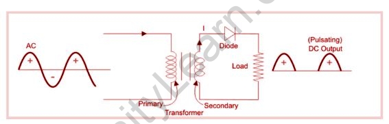
Half Wave Rectifier:
One-half of each AC input cycle is rectified in a half-wave rectifier. When the p-n junction diode is forward biased, it produces little resistance, whereas when it is reverse biased, it produces a lot. When the input voltage is applied for a one-half cycle, the diode is forward biassed, and when the input voltage is applied for the other half cycle, it is reverse biased. The best results can be obtained by switching half-cycles.
Both positive and negative cycles are included in the half-wave rectifier. The current will flow from positive to negative during the positive half of the input, resulting in only a positive half cycle of the AC supply. The voltage at the secondary winding of the diode will decrease when an AC supply is introduced to the transformer. Every one of the variations in the AC supply will be reduced, and the load resistor will receive pulsating DC voltage.
The current will flow from negative to positive in the second half cycle, and the diode will be reverse biased. As a result, no current will be generated at the output, and we will be unable to obtain power at the load resistance. Minority carriers cause a small amount of reverse current to flow during reverse bias.
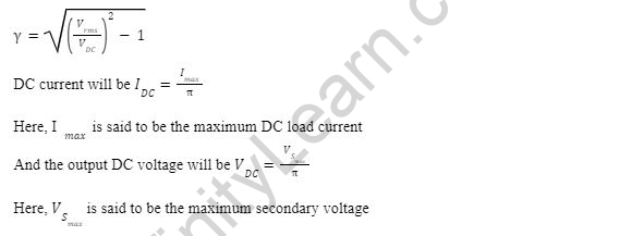
Ripples represent oscillations that occur in DC and are addressed using filters like inductors and capacitors. The ripple factor is used to calculate these ripples, which are denoted by. The ripple factor indicates how many ripples are there in the output DC. The ripple factor determines how much oscillation occurs at the output DC. The lower the ripple factor, the less oscillation occurs at the output DC.
The ratio of the RMS value to the DC value is called the form factor. Here, the form factor of a half-wave rectifier is 1.57.
The ratio of output DC power to input AC power is known as rectifier efficiency. Finally, the efficiency of a half-wave rectifier is 40.6 percent.
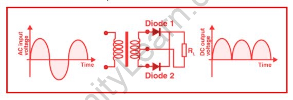
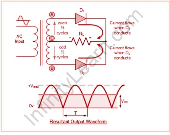
Full Wave Rectifier:
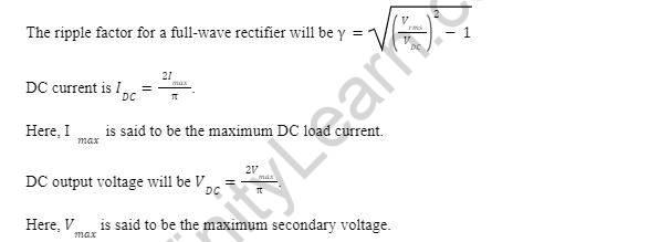
Full-wave rectifier circuits are being used to generate a fully DC output voltage or output current. The major benefit of a full-wave rectifier over a half-wave rectifier is that full-wave rectifiers produce less ripple than half-wave rectifiers because the average output voltage is higher in full-wave rectifiers.
Both halves of each AC input are used by the full-wave rectifier. The diode has low resistance while the p-n junction is forward biased and high resistance when it is reversing biased. The circuit is set up so that if the diode is forward biased in the first half cycle, it is reverse biased in the second half cycle, and so on.
The form factor is defined as the ratio of the RMS current value to the output DC voltage. It is known that 1.11 is the form factor of a full-wave rectifier.
Rectifier efficiency is a parameter used to measure how efficient a rectifier is at converting AC to DC. The ratio of DC output power to AC input power is known as the power factor. A full-wave rectifier’s rectifier efficiency is 81.2 percent.
Diode Rectifier Circuits


Half Wave Rectifier Circuit:
Full Wave Rectifier Circuit:
The Diode Bridge Rectifier
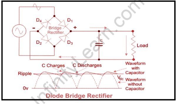
A transformer is being used to step down the voltage to a desirable level, and a load is attached to the output, which consumes energy. The diodes D1 and D3 are forward biased and current flows through them when the top end of the secondary of the transformer is positive. D1 and D3 are forward biased, so current enters through D1 and leaves through D3 to the other terminal. D2 and D4 are also forward biased, so current enters through D2 and leaves through D4 to the source.
The capacitor acts as a filter, removing ripple frequencies and resulting in a DC voltage with a lower ripple frequency. After filtering, we must utilize a voltage regulator to get a controlled DC voltage at the output.
The information about diodes as a rectifier from various physics-related articles is available here. Diode as a rectifier and its general concepts are important topics in physics. Students who want to flourish in physics need to be well known about diodes and rectifiers to get deep knowledge about them to do well on their exams. The definition, types, diagrams, and brief explanations are provided here to assist students in effectively understanding the respective topic. Continue to visit our website for additional physics help.
Also read: Conductors and Insulators
Frequently Asked Questions
What is an uncontrolled Rectifier?
A rectifier is a circuit converter that transforms AC current to DC current. The rectifier circuit is known as the uncontrolled rectifiers circuit since it solely uses diodes. SCR, unlike diodes, does not become or behave like this after conducting when the voltage becomes positive. Gate pulse signals are used to initiate it.
What are the components of a Rectifier?
A rectifier is made up of three parts: a transformer, a stack, and a cabinet. The transformer's job is to safely separate the primary side of the incoming AC voltage from the secondary side, which is then regulated to control the rectifier's output voltage.
What is the reason behind half-wave rectifiers not being used in the dc power supply?
Half-wave rectifiers aren't used for dc power supplies since the supply they give is insufficient.
