Courses

By Shailendra Singh
|
Updated on 18 Nov 2024, 12:54 IST
A meter bridge is an electrical device that can quantify the value of hidden obstacles. It is made of meter wire with a uniform cross-section. These wires are either nichrome or manganese or constantan because they offer high resistance and low coefficient of temperature disturbance. At the Wheatstone connection, a measuring scaffold or sliding wire connection is planned. This is the most basic and useful use of Wheatstone compounds.
The information about Meter Bridge from various physics-related articles is available here. Meter Bridge and its general concepts are important topics in physics. Students who want to flourish in physics need to be well known about Meter Bridge to get deep knowledge about it to do well on their exams. The definition, working principle, and diagram are provided here to assist students in effectively understanding the respective topic. Continue to visit our website for additional physics help.
A meter bridge, also known as a slide wire bridge, is an instrument that works on the principle of a Wheatstone bridge. A meter bridge is used to find the unknown resistance of a conductor, as in a Wheatstone bridge.
Wheatstone bridges, also known as resistance bridges, are used to calculate the resistance of an unknown. This is done by balancing the two different branches of the circuit bridge. One leg has an unknown resistance component. This bridge has two resistors, one with an unknown resistor and the other with a variable resistor.
Bridges are considered reliable because they provide accurate measurements. The bridge consists of four arms and two of them are known and the other two have one variable and unknown resistance. Also, the bridge circuit includes a galvanometer and a source of electromotive force.
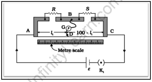
A meter bridge is made of wire 1 m long and equal in cross-section, stretched between two thick metal strips bent at right angles and secured with two gaps through which resistors must be connected. The end to which the wire is fixed is connected to the cell through a key. One end of the galvanometer is connected to a metal strip in the middle between the two gaps.
The other end of the galvanometer is connected to a nose that runs along the wire to create an electrical connection.
R is said to be an unknown resistance connected across one of the gaps.

We join a standard known resistance S across the other gap.
Here, the jockey is joined to some point D on the wire, a distance l1 cm from the end A. The portion AD of the wire has a resistance Rcml1, where Rcm is the resistance of the wire per unit centimeter. The portion DC of the wire similarly has a resistance Rcm100-11. In general, the meter bridge works on the same principle of the Wheatstone bridge.
At balance condition:
R/S=Rcml1/Rcm (100-l1)
=l1/100-l1


Gather the instruments and set up connections.
Counter arithmetic rules are the same as Wheatstone linking rules. Wheatstone connections depend on bad evasion rules. For example, no current will flow through the center arm of the circuit at a point where both arms have the same ratio of protection.
First move the rider to the endpoints of the wire, that is, A and C.
Also read: Important Topic of Physics: Potentiometer
A meter bridge, also known as a slide wire bridge, is an instrument that works on the principle of a Wheatstone bridge. A meter bridge is used to find the unknown resistance of a conductor, as in a Wheatstone bridge.
An end error occurs when any of the metric scale sizes do not match the wire start. This happens because of the movement of zero scales or there is an obstruction in the wire.
Materials like constantan, manganin, or nichrome wires are used in meter bridges because they provide a low coefficient of temperature impermeability.
A meter bridge consists of a uniform wire, a jockey, a galvanometer, and a battery. The known and unknown resistances are connected to the wire, and the jockey is moved to balance the bridge and find the unknown resistance.
The principle behind the meter bridge is the Wheatstone bridge principle, which states that when the bridge is balanced, the ratio of resistances on one side equals the ratio on the other side, minimizing the current flow through the galvanometer.
A meter bridge is used to measure the resistance of an unknown resistor accurately. It is commonly used in physics laboratories for educational purposes and to verify Ohm's law.
By adjusting the position of the jockey along the uniform wire, the bridge is balanced when there is no current through the galvanometer. At this point, the ratio of the known resistance to the distance of the jockey from one end gives the ratio of the unknown resistance to the length of the wire.
A meter bridge provides a relatively simple and accurate method for measuring unknown resistances without complex circuitry. It is also a practical tool for understanding the concept of resistance and electrical balance.
A meter bridge is primarily designed to measure resistances. To measure capacitance or inductance, other specialized devices or setups are required.
While a meter bridge offers a basic level of accuracy, it may not be suitable for very high-precision measurements due to factors like wire resistance and calibration limitations.
Yes, it's possible to create a simple version of a meter bridge using basic materials like a wire, a jockey, and a galvanometer. However, for accurate results, precision instruments and proper calibration are recommended.
Yes, digital multimeters and other electronic measurement devices provide quicker and more precise ways to measure resistances, voltages, and currents compared to traditional meter bridges.