
Table of Contents
Introduction:
Today we are going to learn about LC Oscillations and The Oscillation Formula.
The difference between direct and alternating current is that direct current (DC) only travels in one direction, whereas alternating current (AC) is an electric current that alternates direction on occasion and continuously changes its amplitude over time.
A rectifier circuit converts an alternating current signal to a direct current signal in electronics. But what if we want to take a different path? Is it possible to convert a DC signal to an alternating current signal? Yes, the answer is yes. So, in essence, an oscillator circuit is a circuit that converts a DC signal to an AC signal.
Overview:
When an inductor is linked to a charged capacitor, the electric current and charge on the capacitor oscillate in the circuit. The process repeats at a set frequency, and if there is no resistance in the LC circuit, the LC Oscillations will go on eternally.
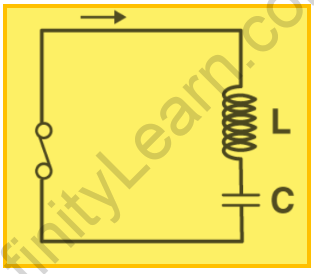
A tank circuit (comprising an inductor and a capacitor) is used in the LC Oscillator to give the necessary positive feedback to keep oscillations in a circuit continuing. As the name implies, a charged capacitor (C) is linked to an uncharged inductor (L) in this circuit, as shown below.
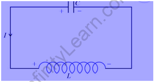
When a charged capacitor is coupled to an inductor, the electric current and charge on the capacitor in the circuit undergo electrical LC oscillations. The capacitor’s initial charge, known as qm, represents the electrical energy it stores.
It is symbolized by,
U E=1/2 q m² /C
There is no energy in the inductor. With respect to time, charge varies sinusoidally.
When the switch is turned on, the current in the circuit begins to increase while the charge on the capacitor continues to decrease. The induced current in the circuit creates a magnetic field in the inductor.
When the current reaches its maximum Im, the magnetic energy in the circuit is represented as follows:
UB=1/2LIm²


LC oscillator circuit
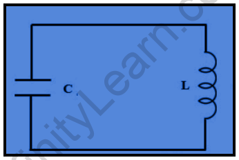
An LC circuit is an electric circuit that can be built with an inductor and a capacitor, where the inductor is denoted with the letter ‘L’ and the capacitor is denoted with the letter ‘C,’ both of which are allied within a single circuit.
The circuit functions as an electrical resonator, storing energy to oscillate at the circuit’s resonant frequency. These circuits are used to either select a signal at a specific frequency via the compound signal or to generate signals at a specific frequency.
These circuits function as major components in a wide range of electronic devices, including radio apparatus and circuits such as filters, tuners, and oscillators. This circuit is a perfect model that assumes that energy dissipation does not occur due to resistance.
The main purpose of this circuit is to oscillate with the least amount of damping possible in order to minimise resistance.
LC oscillation formula
Using Kirchhoff’s Voltage Law in the tank circuit, we can conclude that the sum of the potential differences across the capacitor and inductor will be equal to zero.
VL+VC=0
-Ldi/dt+q/C=0
i=-dqdt because the charge on the capacitor decreases over time:
Ld²q/dt²+q/C
=0 d²q/dt²
=-q/LC
This is referred to as the differential equation for LC Oscillations.
The angular frequency of LC oscillations can be calculated using this equation:
ω=1/√LC
As a result, its frequency will be:
f=1/2π√LC
The LC Oscillation differential equation will have the following solution:
q=qmsin(ωt+Φ)
To summarise the entire article, LC Oscillations are caused by LC Oscillator circuits. It is also known as tank circuits, which consist of a capacitor and an inductor. Energy transfer continues between the capacitor and inductor, but the total energy of the LC oscillations remains constant. Because of the continuous transfer of energy from the capacitor to the inductor and from the inductor to the capacitor, the current direction eventually changes according to the polarity of charging and discharging, resulting in an alternating signal.
Also read: Power Factor in AC Circuit
FAQs:
Question 1: What occurs in LC Oscillations?
Answer 1: LC oscillations are caused by the continuous transfer of energy from the capacitor (C) to the inductor (L).
Question 2: What causes LC oscillations to be non-realistic?
Answer 2: Because inductors and capacitors are obviously non-ideal, they will have some resistance in them in real life.
