
Table of Contents
Inductance is the tendency of an electrical conductor to resist changes in the electric current passing through it. The flow of electric current creates a magnetic field around a conductor. The field strength is proportional to the magnitude of the current and follows any changes in current. According to Faraday’s law of induction, any change in the magnetic field via a circuit generates an electromotive force (EMF) (voltage) in the conductors, a process is known as electromagnetic induction. The induced voltage generated by the changing current acts to cancel out the current change.
This is stated by Lenz’s law, and the voltage is referred to as back EMF. The ratio of the induced voltage to the rate of change of the current creating it is known as inductance. It’s a proportionality factor that’s influenced by the geometry of circuit conductors as well as the magnetic permeability of adjacent materials. An inductor is a type of electronic component that adds inductance to a circuit. It’s usually made out of a wire coil or helix. Self-inductance is a type of electromagnetic induction with a unique feature. The induction of a voltage in a current-carrying wire when the current in the wire changes is known as self-inductance. The magnetic field formed by a changing current in the circuit itself induces a voltage in the same circuit in the case of self-inductance. As a result, the voltage is induced by itself. A coil of wire is a fairly common inductor, and the term inductor is used to designate a circuit device that has the attribute of inductance. In most circuit diagrams, an inductive component is represented by a coil of wire. Understanding why a voltage is induced in a wire carrying a changing current requires a deeper look at a coil. As the current changes, the alternating current in the coil creates a magnetic field in and around the coil that increases and decreases.
Overview
The trait of a current-carrying coil that resists or opposes the change in current flowing through it is known as self-inductance. This is primarily owing to the self-induced emf generated by the coil. Self-inductance is a phenomenon that occurs when a voltage is inducted in a current-carrying wire. When the current rises, the self-induced emf in the coil resists the rise, and when the current falls, it also resists the fall. In essence, if the current is growing, the induced emf is in the opposite direction of the applied voltage, and if the current is decreasing, the induced emf is in the same direction as the applied voltage. The coil’s aforementioned attribute applies only to alternating current, which is a changing current, and not to direct or stable current. Self-inductance, which is measured in Henrys, is always in opposition to the changing current (SI unit). Induced current always opposes the change in current, whether the current in the circuit is increasing or decreasing.
Self-inductance is part of electromagnetic induction.
An electromotive force is induced when the current or magnetic flux of the coil changes. Self Inductance is the name given to this occurrence. When electricity begins to flow through the coil at any point in time, the magnetic flux is found to be directly proportional to the current flowing through the circuit. The relationship is as follows:
Φ = L I
The self-inductance of the coil, also known as the coefficient of self-inductance, is determined by the cross-sectional area, material permeability, or the number of turns in the coil. The rate of change of magnetic flux in the coil can be calculated as follows:
Self-inductance basics
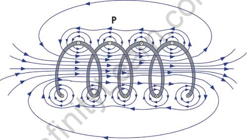
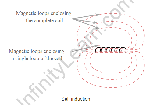
A magnetic field is induced when current flows along a wire, particularly when it passes through a coil or inductor. This extends from the wire or inductor and may connect to other circuits. It does, however, coupled with the circuit from which it is set up. The magnetic field can be visualised as concentric loops of magnetic flux that surround the wire, as well as larger loops that connect with others from other loops of the coil, allowing self-coupling within the coil. When the current in the coil changes, a voltage is induced in the coil’s various loops as a result of self-inductance.
In terms of quantifying the effect of inductance, the basic formula below does so.
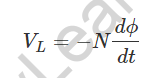
Where VL denotes the induced voltage in volts.
N = number of turns in the coil
dφ/dt = magnetic flux rate of change in webers per second
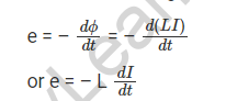
The induced voltage in an inductor can also be expressed in terms of inductance (in henries) and the current rate of change.
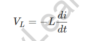
Single coils and chokes use self-induction to operate. A choke is used in radio frequency circuits because it opposes any change, such as the radio frequency signal while allowing any steady current, such as DC current, to flow.


Self-inductance of a Solenoid
With the help of an example, we will grasp the concept. Let us consider a solenoid with N turns, with length ‘l’ and area of cross-section ‘A’ where current I flows through it. At any point in the solenoid, there will be a magnetic field ‘B.’ As a result, the magnetic flux per turn is equal to the B area of each turn.
So, B = (μ0NI)/l
As a result, magnetic flux per turn=(μ0NIA)/l
The total magnetic flux (φ) connected to the solenoid will now be given by the product of the flux present through each turn and the total number of turns.
Φ = (μ0NIA) x N /l
So, Φ = (μ0N2IA) /l
If L is the solenoid’s self-inductance, then
Φ = LI
Combining the above equations
L = (μ0N2A) /l
If you have a core made of magnetic material with permeability μ, then
L = (μN2A) /l
Mechanical Equivalent of Self-inductance
The self-induced emf, also known as the back emf, opposes any change in current in a circuit. Self-inductance acts as inertia in a physical sense. It is also the electromagnetic analogue of mass in mechanics. As a result, work must be done against the back emf (VL) to establish the current. This work is recorded as magnetic potential energy and is provided by:
W = (1 / 2) LI2.
This is the amount of energy required to generate a current I in the inductor. This expression is analogous to mv 2 /2 for the (mechanical) kinetic energy of a particle of mass m and demonstrates that L is analogous to m. (i.e., L is electrical inertia and opposes both the growth and decay of current in a circuit).
Uses of Self Inductance
An inductor’s primary function is to store electrical energy in the form of a magnetic field. Inductors are used in the following applications:
- Circuits for tuning
- Sensors
- Energy can be stored in a device.
- Motors with induction rotors
- Transformers
- Filters, Chokes, and Ferrite Beads
- As relays, inductors are used.


FAQ’s
What is the difference between self and mutual inductance?
The change in current strength in the coil is opposed by the coil itself by inducing an e.m.f. in self-inductance. Mutual inductance occurs when one coil opposes changes in the strength of the current flowing through the other coil.
What is the purpose of self-induction?
The self-inductance of a circuit describes the circuit's reaction to a changing current in the circuit, whereas the mutual inductance with respect to a second circuit describes the second circuit's reaction to a changing current.
What exactly is self-induction with an example?
Because self-inductance is associated with the magnetic field produced by a current, any conductor configuration has self-inductance. A long, straight wire, for example, has self-inductance in addition to the wire loop, as does a coaxial cable.