
Table of Contents
A transistor is said to be a semiconductor device that is used to boost or switch electrical signals and power. We can say, the transistor is a fundamental building block of modern electronics. It really is typically made of semiconductor material and has at least three terminals for connecting to an electronic circuit. A voltage or current adhered to one pair of terminals of the transistor controls the current through another pair of terminals. A transistor can amplify a signal because the controlled (output) power can be greater than the controlling (input) power. Some transistors are packaged separately, but many more are embedded in integrated circuits. Electronic transistors were indeed small devices that regulate the flow of current in a circuit. Transistors are very important electronic components used in circuits because they can be modified to function as other electronic components such as switches, oscillators, and so on. A transistor can also be used as an amplifier in the same way. When the input signal to a circuit is weak, it is used.
Overview
In general, an amplifier, as well known as an electronic amplifier or (informally) amp, is a type of electronic device that can boost the power of a signal (a time-varying voltage or current). This is a two-port electronic circuit that uses power from a power supply to increase the amplitude of a signal applied to its input terminals, resulting in a signal with proportionally greater amplitude at its output. The quantity of amplification provided by an amplifier is measured by its gain, which is the ratio of output voltage, current, or power to the input voltage, current, or power. A circuit with a power gain greater than one is referred to as an amplifier. An amplifier could be a standalone piece of equipment or an electrical circuit embedded in another device. Amplification is essential in modern electronics, and amplifiers are found in almost all electronic devices. Amplifiers are being categorized in a variety of ways. One method is to increase the frequency of the electronic signal being amplified.
An electronic oscillator is indeed a circuit that generates a periodic, oscillating electronic signal, typically a sine wave, square wave, or triangle wave. Oscillators are said to be the devices that convert direct current (DC) from a power supply to alternating current (AC). They have been widely used in a wide range of electronic devices, from simple clock generators to digital instruments (such as calculators) and complex computers and peripherals, among others. An oscillator that generates AC power from a DC supply is commonly referred to as an inverter in AC power supplies. Prior to the introduction of diode-based rectifiers, an electromechanical device that converted AC power to DC was referred to as a converter, though the term is now more commonly used to refer to DC-DC buck converters.
Transistor as an amplifier (common emitter configuration)
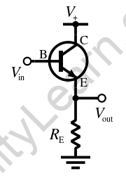
A transistor amplifier is really a configuration in which an NPN transistor is configured in a common emitter configuration. Transistor amplifiers are transistor circuits that can increase the strength of the input signal in the circuit. This is also referred to as a Common Emitter Transistor or an Amplifier. The operation of a transistor amplifier necessitates knowledge of amplification and amplifier.
We use a weak input signal between the emitter-base junction and take the output across the load Rc connected in the collector circuit. Always ensure that the input circuit is forward-biased and the output circuit is reverse-biased for maximum amplification. In addition to the signal, we use D.C voltage, i.e. VEE, in the input circuit for this purpose.
Such a D.C voltage is known as a bias voltage and its magnitude is such that it always keeps the input circuit forward-biased despite the polarity of the signal. Because the input circuit has a low resistance, a small change in the signal voltage causes an appreciable change in the emitter current. A change in emitter current causes a similar change in the collector circuit due to transistor action.
The collector current flowing through a high load resistance Rc now generates a large voltage across it. As a result, the weak signal applied in the input circuit is amplified in the collector circuit. In this manner, the transistor functions as an amplifier.


Common Emitter Amplifier Working:
In most electronic circuits, the most common circuit configuration for an NPN transistor (Common emitter Amplifier circuit) has been used.
Transistor Amplifier Biasing:
Consider the circuit of a single stage common emitter amplifier. It is also known as the voltage divider biasing circuit. This biassing configuration essentially employs two resistors as a potential divider network across the supply, with their centre point supplying the required base bias voltage to the transistor. Bipolar transistor amplifier circuits frequently employ this type of biassing. By holding the base bias at a constant steady voltage level, this type of biassing greatly reduces the effect of the current amplification factor and allows accurate stability. The potential divider network formed by the two resistors and the power supply voltage Vcc is used to calculate the base voltage Vb.
The net or total resistance is equal to the sum of the first and second resistances, R1 and R2. The voltage level produced at the junction of resistors R1 and R2 maintains the base voltage constant at a value less than the supply voltage. Using the simple voltage divider formula, the bias reference voltage can be calculated as:
Vb = (Vcc R2) / (R1 + R2)
When the transistor is switched “Fully-on,” i.e. in saturation mode, the same supply voltage determines the maximum collector current.
CE transistors, like other transistors, have various characteristics such as gain, resistance, and impedance.
The ratio of the change in input voltage to the change in amplifier output voltage is equal to common emitter voltage gain. Regard Vout to be a ΔVL and Vin to be a ΔVB. Voltage gain is equal to the ratio of the signal resistance in the collector to the signal resistance in the emitter, which is given in terms of resistances as:
Voltage Gain = Vout / Vin = Δ VL / Δ VB = – RL / RE
As we all know, bipolar transistors have a small internal resistance, Re, built into their emitter region. Whenever the internal emitter resistance is connected in series with the external resistance, the voltage gain equation is modified as follows:
Voltage gain = – RL / (RE + Re)
At lower frequency, the total resistance in the emitter circuit equals the sum of the internal and external resistances, RE + Re. The voltage gain at high and low frequencies for this common-emitter amplifier circuit is given as:
Voltage Gain = – RL / RE
Transistor as an oscillator
An oscillator is a type of electronic circuit that generates a periodic, oscillating signal, most commonly a square wave and a sine wave. It essentially converts direct current from a power supply to alternating current.
If we use a transistor in a circuit, it continuously generates undamped oscillations at the circuit’s output terminals.
One such circuit is broken down into three sections:
(i) Tank Circuit: One such circuit generates oscillations that are amplified by the transistor, resulting in amplified output on the collector side.
(ii) Amplifier circuit: Such a circuit amplifies the small sinusoidal oscillations present in the base-emitter circuit and produces amplified output.
(iii) Feedback circuit: It is an essential part of the circuit because we need some energy from the tank circuit to amplify the oscillations for the amplifier. We used the phenomenon of mutual induction to feedback the energy from the collector circuit to the base circuit for this purpose. With the help of this circuit, we were able to feedback energy from the output to the input.


Working of Transistor Oscillator circuit:
During oscillator circuit design, a transistor is often used as a common-emitter circuit, with the emitter shared by the base and collector terminals. A tank circuit has been connected between the input terminals, i.e. between the emitter and the base. The tank circuit is an electric circuit in which an inductor (L) and a capacitor (C) are connected in parallel, causing the circuit to oscillate. The base current fluctuates as a result of the oscillations of voltage and charges in the tank circuit, and as a result of this fluctuation, the forward biassing of the base current varies on a regular basis. As a result, the collector current begins to vary on a regular basis. Quite accurately, the LC oscillations are sinusoidal in nature, and as a result, both the collector current and the base current are very sinusoidally. If indeed the collector current varies sinusoidally, the output voltage obtained can be written as Ic RL and considered to be sinusoidal. Once we draw a graph between the output voltage Vout and time, we get a sinusoidal curve. Now, in order to have continuous oscillations in the tank circuit, we need some energy, but there is no battery or dc source available in this circuit. To accomplish this, we connect mutual inductor L2 and L1 in the collector and base circuits using a soft iron rod. Such a soft iron rod will connect inductor L2 to inductor L1, and due to mutual induction, some of the energy in the collector circuit will be transferred to the base side of the inductor. As an outcome, the oscillation in the tank circuit is sustained and amplified indefinitely.
![]()
FAQs
Can a transistor be used as an amplifier?
Among the most significant properties of a transistor, one is its ability to function as an amplifier. Transistors can function as amplifiers when they are in the active region or when they are properly biassed.
What is the application of a transistor as an amplifier?
In optical fibre communication, transistors are used as amplifiers. Because the output signal has a high intensity, it is useful for long-distance communication. Such amplifiers allow for the amplification of radio signals.
What is the role of transistors in a piezoelectric oscillator?
Electrical oscillations are continuously produced with the help of other electronic components such as a transistor. It is supplied into the secondary circuit, which is linked to the Quartz crystal (Q). The piezoelectric effect converts the oscillating electric field to the mechanical vibration of the crystal.
