Table of Contents
Introduction:
V-I characteristics stand for voltage-present day characteristics of an electrical issue or device. The v-i graph yields valuable statistics approximately the resistance and breaks down a digital aspect. It also provides the working area of an element.
Overview
With the aid of reading those traits, we are able to apprehend where and how to use a thing in an electric circuit. The voltage-ampere traits of an electronic factor are its behavior for various values of an carried out voltage. Positioned clearly; it’s far from the graph among voltage and current obtained whilst modern is measured through an electronic issue as a voltage is carried out across it.
In v-i traits, the voltage, v is on the x-axis, and the cutting-edge, I is at the y-axis because it is easier to govern the applied voltage rather than the present day. This makes the voltage the independent variable and is as a result historically positioned on the x-axis.
Types of V-I Characteristics
- Linear VI Characteristics
A linear vi curve has a steady slope and for this reason a constant resistance. Carbon resistors and metals obey ohm’s regulation and have regular resistance. This means that the v-i curve is an immediate line passing through the starting place. An electronic thing might also showcase linear traits only in a selected place. For instance, a diode has a basically linear behavior in its running region.
- Non-linear VI Characteristics
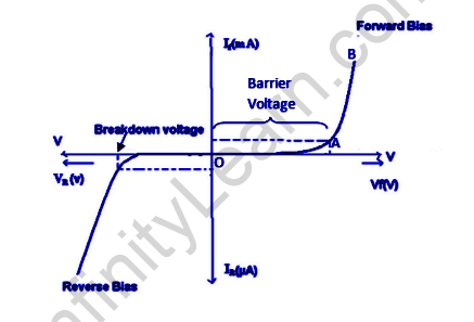
A circuit factor has a non-linear characteristic if the resistance isn’t regular in the course of and is a few functions of voltage or modern. The diode, as an example, has various resistance for one-of-a-kind values of voltage. However, it has a linear function for a narrow running location. Note that in the graph beneath we can also see the maximum forward and opposite voltage wherein the diode can be operated without inflicting breakdown and burning up of the diode.
V-I Characteristics of PN Junction Diode

Vi characteristics of PN junction diodes is a curve among the voltage and current through the circuit. Voltage is taken alongside the x-axis while the modern-day is taken along the y-axis. The above graph is the vi traits curve of the PN junction diode. With the assist of the curve we are able to take into account that there are 3 regions in which the diode works, and they’re:
- Zero bias
- Forward bias
- Reverse bias
When the outside voltage connects the p-type to the positive terminal and the n-type to the negative terminal in a forward bias situation, the PN junction diode is reduced in its potential barrier, which allows for the flow of current.
SILICON DIODES
For silicone diodes, whilst the voltage is zero. 7 v and for germanium diodes, whilst the voltage is 0. 3 v, the capacity obstacles lower and there is a float of the present day. Whilst the diode is in ahead bias, the current increases slowly and the curve acquired is non-linear as the voltage implemented to the diode is overcoming the capacity barrier.
The minority carriers have increased kinetic energy when the applied voltage is increased, which affects the bulk charges, breaking down the diode, and potentially damaging it. This occurs when the PN junction diode is below poor bias condition, with the p-kind attached to the negative terminal and the n-kind attached to the positive terminal of the applied voltage, allowing the capacity barrier to be conquered with the aid of the diode, resulting in a sharp rise in the curve as the outside voltage increases and a linear curve is obtained.
V-I Characteristics of Zener Diode
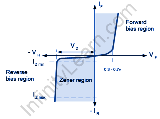
The diagram given below shows the V-I characteristics of the Zener diode.

Reverse-biassing a Zener diode allows only a small amount of leakage current until the voltage is less than the Zener voltage.
Zener diodes can be categorized into two groups based on their V-I characteristics:
(i) Forward Characteristics
(ii) Reverse Characteristics
Forward Characteristics of Zener Diode
The first quadrant withinside the graph represents the ahead traits of a Zener diode. From the graph, we apprehend that its miles are nearly the same as the ahead traits of another P-N junction diode.
Reverse Characteristics of Zener Diode
We start with a small opposite saturation and carry out an opposite voltage to a Zener voltage, causing a current (Io) to flow through the diode due to thermally generated minority carriers. As the opposite voltage is increased, a sudden and significant increase in the opposite current will occur at a certain voltage, indicating a breakdown has taken place. We refer to this voltage as the breakdown voltage of the Zener voltage, denoted by Vz.
V-I characteristics of LED
We recognize LED is an ahead-biased p-n junction diode that emits mild while strength is applied. This mild power is produced because of the recombination of holes and electrons on the junction of a diode. If an LED is attached in an opposite biased condition, it’s going to now no longer emit mild. Moreover, the LED can be broken in opposite biased conditions.
Mechanism of spontaneous emission explains the mechanism of emission of mild power from an LED. We recognize that there are exceptional power bands found in a semiconductor, conduction band with better power and valence band with decreased power. Also, there can be power bands because of donor impurities(ED)close to the conduction band and acceptor impurities(EA)
close to the valence band. When electrons transit from a better to decrease power level, mild power is released.
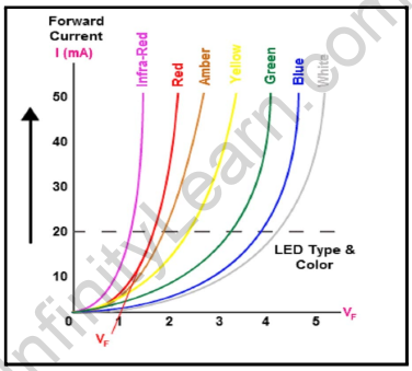
Now, the V−I traits of LEDs are much like the ones of a diode related in ahead biassed conditions. That is,

As we know, V-I traits are regarded for voltage-present day traits of an electrical issue or device. The V-I graph yields treasured statistics approximately the resistance and break down a digital issue. It additionally offers the working place of an issue. In V-I traits, the Voltage, V is at the x-axis, and the present day, I is at the y-axis due to the fact it’s miles less complicated to manipulate the carried out voltage in place of the present day. This makes the voltage the unbiased variable and is consequently historically located at the x-axis.
Also read: Important Topic of Physics: Specific Heat Capacity
FAQs
What is the conclusion of VI characteristics of the PN junction diode?
Current flows through the diode with an increase in voltage during forward bias. Diodes do not conduct when a reverse bias is applied.
Why is Zener Diode used as a regulator?
Zener diodes are used as shunt voltage regulators. When the Zener diode exceeds the knee voltage, the voltage across the load remains constant once it is connected parallel to the load.


