
Table of Contents
I-V Characteristics in Forward and Reverse Bias: What is forward and reverse bias? What happens when a diode is forward or reverse biased? Let us try to look into these aspects in this article.
A forward biased diode conducts current (IF) in the forward direction. The amount of forwarding voltage has a direct effect on the value of IF. In fact, the ampere-volt, or IV, characteristic of a diode is the relationship between forwarding voltage and forward current. This operation generates excessive heat across the junction, which can destroy a diode. A protective resistor is connected in series with the diode to avoid this situation. The forward current is limited by this resistor to its maximum rated value. When diodes are operated in the forward direction, a current-limiting resistor is typically used.
When a diode is reverse biased, it conducts a small amount of reverse current. In a graph, the vertical reverse current line has current values expressed in microamperes. The number of minority current carriers involved in reverse current conduction is quite small. Overall, this means that the reverse current is constant over a large portion of the reverse voltage range whenever the reverse voltage of a diode is increased from the start, the reverse current changes very slightly. Current increases very quickly at the breakdown voltage (VBR) point. At this point, the voltage across the diode remains relatively constant. One such constant-voltage characteristic enables a variety of diode applications under reverse bias conditions. Avalanche breakdown and Zener breakdown are the processes that are responsible for current conduction in a reverse-biased diode.
For forward and reverse bias operations, various current scales are available. The forward portion of the curve shows that when the P-region is made positive and the N-region is made negative, the diode conducts simply. When the P-region is made negative and the N-region is made positive, the diode conducts almost no current in the high resistance direction. The holes and electrons are now being drained away from the junction, raising the barrier potential.
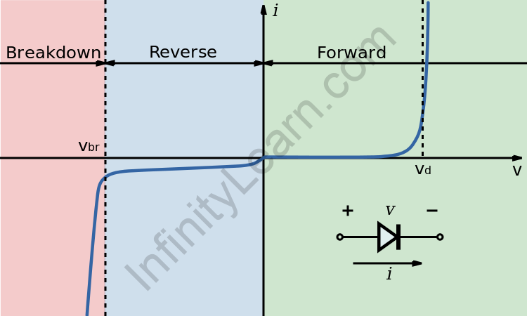
The reverse current portion of the curve indicates this condition. A diode’s forward and reverses current-voltage (IV) characteristics are commonly compared on a single characteristic curve. Forward Voltage and Reverse Voltage are typically plotted on the horizontal line of the graph. The graph’s vertical axis displays forward and reverses current values. The graph’s starting point, or zero value, is in the centre. Forward Current grows above the horizontal axis, while Reverse Current grows downward.
I-V Characteristics in Forward and Reverse Bias
A semiconductor diode’s primary function, for example, is the rectification of AC to DC. When a diode is forward biased (the higher potential is connected to the Anode), current flows through it. The current is blocked when the diode is reverse biased (the higher potential is connected to the Cathode). A PN junction needs a bias voltage of a specific polarity and amplitude for current to flow. Such a bias voltage also controls the resistance of the junction and, as a result, the current flow through it.
Once the diode is forward biased, or anode positive in relation to the cathode, a forward or positive current flows through it and operates in the top right quadrant of its I-V characteristics curves. The curve gradually increases into the forward quadrant from the zero intersection, but the forward current and voltage are extremely small.
The operational region is in the first quadrant in the forward bias. Germanium has a threshold voltage of 0.3 V and Silicon has a threshold voltage of 0.7 V. Beyond this threshold voltage, the graph rises in a non-linear fashion.
At the time when the forward voltage exceeds the internal barrier voltage of the diode’s P-N junction, which for silicon is about 0.7 volts, an avalanche occurs and the forward current increases rapidly for a very small increase in voltage, resulting in a non-linear curve. The forward curve’s “knee” point.
Similarly, when the diode is reverse biased, cathode positive in relation to the anode, it blocks current except for a very small leakage current and operates in the lower left quadrant of its I-V characteristic curves. The diode persists in blocking current flow until the reverse voltage across the diode exceeds its breakdown voltage point, resulting in a sudden increase in reverse current and a fairly straight line downward curve as voltage losses control. Such a reverse breakdown voltage point works well with Zener diodes.
It’s because of minority carriers. This voltage is sufficient for the minority carriers to break through the depletion region. A strong current will flow through this junction in this case. There are two types of voltage breakdowns:
- Avalanche Breakdown: this is not a sharp graph, but rather an inclined linear graph, in which a small increase in reverse voltage causes more sharp current gradually after the breakdown.
- Zener Breakdown: Because current flows sharply, there is no need to increase the reverse bias voltage to get more current.
The I-V Characteristic can then be seen. Because their electrical characteristics differ, the curves for a silicon diode are non-linear and very different from the previous resistors’ linear I-V curves. The arcs or curves of current-voltage characteristics can be used to plot the operation of any electrical or electronic component, from resistors to amplifiers, semiconductors, and solar cells.
The current-voltage characteristics of an electrical component tell us a lot about how it works and can be a very useful tool in determining the operating characteristics of a specific device or component by showing its possible combinations of current and voltage, and as a graphical aid can help visually understand what is going on within a circuit.
Join our JEE 2024 Course to make your IIT dream come true.
FAQs
How do you identify forward and reverse bias of a diode?
Positive voltage indicates that the diode is forward biassed whereas negative voltage indicates that the diode is in reverse bias mode.
What is a VI characteristic?
The voltage-current characteristics of an electrical component or device are referred to as V-I characteristics. The V-I plot provides useful information about resistance and deconstructs an electronic component.
What is the IV characteristics of a diode?
A forward biassed diode conducts current (IF) in the forward direction. The amount of forwarding voltage has a direct effect on the value of IF. In general, the ampere-volt, or IV, characteristic of a diode is the relationship between forwarding voltage and forward current.
Infinity Learn App
Now you can find answers to all your subject queries & prepare for your Exams on our Ultimate Learning App – Infinity Learn.
