
Table of Contents
Introduction
The amount of separated electric charge that may be stored on an electric conductor (or set of conductors) per unit change in electrical potential is measured by capacitance. Capacitance also denotes the ability to store electrical energy. When an electric charge is transmitted across two initially uncharged conductors, both become evenly charged, one positively, the other negatively, and a potential difference in them is established. The capacitance C is equivalent to the ratio of the charge q on each conductor to the electrical potential V between them, or simply C = q/V.
A brief outline
A capacitor is a device that is used to intentionally introduce capacitance into electric circuits. As a result, a capacitor, also known as a condenser, is essentially a sandwich of two conducting plates separated by an insulating layer, or dielectric. The main purpose of this device is to store electrical energy. The size and geometrical layout of the plates, as well as the type of dielectric material utilized, varied between capacitors. Mica, paper, ceramic, air, and electrolytic capacitors are some of the names given to them. For use in tuning circuits, their capacitance can be set or changeable over a range of values.


Important concepts
The capacitance of a parallel plate capacitor
An arrangement of electrodes and an insulating substance or dielectric constitute parallel plate capacitors. Before the dielectric breakdown, a parallel plate capacitor can only hold a finite quantity of energy. The parallel plate capacitor is defined as follows: When two parallel plates are linked across a battery, the plates are charged, and also an electric field is established among them.
The formula for a Parallel Plate Capacitor
The direction of the electric field is defined as the flow of the positive test charge in that direction. The body’s ability to hold an electric charge is limited by capacitance. Capacitance is a property of every capacitor. A typical parallel-plate capacitor is made up of two metallic plates with an area of A and a distance of d between them.
C = kϵoA/d
Where,
ϵo = permittivity of space (8.854 × 10⁻¹² F/m)
k = relative permittivity of dielectric material
d = separation between the plates
A = Area of plates


Derivation of a Parallel Plate Capacitor
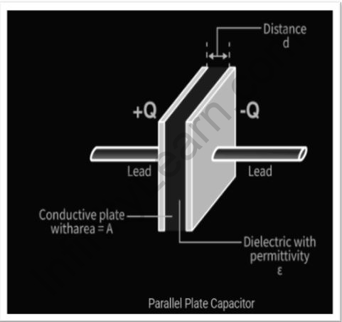
A parallel plate capacitor can be seen in the figure below. Two huge plates are parallel to one other and separated by a modest distance d. As demonstrated by the dotted array, the space between the plates is filled with a dielectric substance. The two plates are charged in the same way but in opposing directions.
The first plate has a charge of +Q, whereas the second plate has a charge of –Q. Each of the plates has an area of A, and the distance between them is d. The distance d is much smaller than the area of the plates, so we can write dA. As a result, the effect of the plates is treated as that of an infinite plane sheet with uniform surface charge density, and the electric field generated by them is treated as that of an infinite plane sheet with uniform surface charge density. The surface charge density can be calculated using the total charge on plate 1 as Q and the area of the plate as A.
σ = Q/A
Likewise, for plate 2 with a total charge equal to –Q and area A, the surface charge density can be written as,
σ = – Q/A
The areas around the parallel plate capacitor are divided into three parts: area 1 is to the left of the first plate, area 2 is between the two planes, and area 3 is to the right of plate 2.
The electric field is consistent throughout and runs from the positive plate to the negative plate in this case. By multiplying the electric field by the distance between the planes, the potential difference all across capacitors may be computed.
V = E*d = 1/ϵ * Qd/A
The parallel plate capacitor’s capacitance can be written as,
C = Q/V = ϵ0A/d
There are many different types of capacitors on the market, some of which include:
Variable capacitor – We can change the capacitance value of this type of capacitor electronically. They’re most commonly found in LC circuits.
It’s a non-polarized capacitor called a trimmer capacitor.
A film capacitor is a capacitor having a dielectric and an insulating plastic film.
Ceramic capacitors are made up of two or more layers of ceramic and metal that alternate. They are non-polarized and have a high level of stability.
Polypropylene capacitor – The dielectric of this capacitor is a polypropylene film. It’s a functional capacitor with a high voltage.
Significance of capacitance of a parallel plate in the IIT JEE exam
Electrostatic Potential and Capacitance account for roughly 35.6 percent of the total weight. Modern physics and semiconductors, optics, and electrostatics (all of which are larger chapters) are given more weight in class 12. Despite the fact that modern physics is the most popular chapter in class 12, students find it to be the most difficult. As a result, make sure you devote adequate time and attention to it. The percentage of questions from class 11 in the February and March 2021 examinations was slightly greater (49.6 percent compared to about 48 percent on an average in 2020 and 2019 papers).
FAQs
An electrical conductor is a material that is a carrier of current when a voltage is applied, whereas a capacitor is a passive device in a circuit that can store electricity in the form of electrostatic charges. Between the metal plates of a capacitor is an insulating material called a dielectric. In conductors, however, there really is no insulation/resistance or idea of the dielectric.
Yes, in the context of this discussion, capacitors and condensers are interchangeable. Because both phrases do the same thing, the capacitor has simply replaced the term condenser.
In comparison to a system with capacitors connected in series, connecting capacitors in parallel allows the circuit to store more energy. Because the overall capacitance of the system is equal to the sum of the individual capacitances of all the capacitors parallel connected, this is the case. What makes a capacitor different from a conductor?
Is there a difference between a capacitor and a condenser?
What are the benefits of employing parallel capacitors?


Infinity Learn App
Now you can find answers to all your subject queries & prepare for your Exams on our Educational App – Infinity Learn.
