
Table of Contents
Introduction:
A closed path through which electrons move to produce electric currents is known as an electric circuit. Electric circuits are significant ideas with real-world implications in our everyday lives. It’s a straightforward notion that consists of three parts: an electrical energy source, a gadget, and a closed-loop of conducting material.
In an electrical circuit, an ammeter, galvanometer, and voltmeter are all used to measure distinct characteristics of electricity. An ammeter measures current, a voltmeter aids in the calculation of the voltage or potential difference between two points in an electric circuit, and a galvanometer is a highly sensitive device for detecting current.
Overview:
The source of electrical energy that allows electrons to move is the initial component in an electric circuit. A battery, a solar cell, or a hydroelectric plant anything with a positive and negative terminal from which charge may flow from one to the other could be this source. Voltage is the term for the push of electric charge, and its potential is measured in volts.
The electrical current is the flow or movement of electrons through an electrical circuit. Amperes are considered as the units of measurement for current.
Another word that comes to mind while thinking about electricity is power. Work divided by time is the definition of power. Power is equivalent to current voltage, measured in watts, in an electrical circuit. The higher the wattage, whether it’s a light bulb, an amplifier, or any other electrical gadget, the faster it consumes energy.
The information about ammeter, galvanometer and voltmeter from various physics-related articles are available here. Ammeter, galvanometer, and voltmeter and their general concepts are important topics in physics. Students who want to flourish in physics need to be well known about ammeters, galvanometers and voltmeters to get deep knowledge about it to do well on their exams. The general definitions, types, conversions, and differences are provided here to assist students in effectively understanding the respective topic. Continue to visit our website for additional physics help.


Ammeters:
Ammeters were laboratory equipment whose operation was reliant on the earth’s magnetic field. The ammeter, which could be mounted in any position and could take accurate measurements, was invented in the nineteenth century. An ammeter is a device that measures current, either alternating or direct.
Ampere is considered as the unit of current, as we all know. This instrument is known as an ammeter because it measures the value in amperes.
The ammeter is usually linked in series with the circuit to measure the current. The current is measured in the milliampere or microampere range, and this device is mostly used for monitoring a small quantity of current.
The milliammeter is a device for measuring current in milliamperes, while the microammeter is a device for measuring extremely small electric currents calibrated in microamperes. The ammeter is symbolized by the letter “A” in a circuit.
Ammeters always have low resistance, and an ideal ammeter has zero internal resistance. It has a low internal resistance in general.
The device is equipped with a built-in fuse that protects it against high currents. The fuse will blow if a large amount of current goes through the ammeter. Until the replacement fuse is installed, the ammeter will not be able to measure the current.
It is categorized into the following categories based on the current passed:
- AC ammeter
- DC ammeter
The ammeter is classed as follows based on its design and manufacturing pattern:
- Permanent moving coil ammeter
- Moving iron ammeter
- Electro-dynamometer ammeter
- Rectifier type ammeter
To measure the whole flow of electrons, an ammeter is connected in series with the circuit (current). The device’s power loss is caused by the measured current and the ammeter’s internal resistance. The ammeter circuit has a low resistance, resulting in a low voltage drop in the circuit.
Voltmeter:
A voltmeter, often known as a voltage metre, is a device that detects the difference in voltage or potential between two points in an electronic or electrical circuit. Voltmeters are typically used to test either AC or DC circuits. Alternatively, specialized voltmeters can be used to measure Radio Frequency (RF) voltage. Voltages are measured with voltmeters, millivoltmeters (0.001 volts), and kilovoltmeters (1,000 volts).
A voltmeter is connected in parallel with a device in order to measure its voltage. This is critical because parallel objects are more likely to have the same potential difference. Because it has the same voltage drop as the circuit, it is linked in parallel with it.
The internal resistance of a voltmeter is likewise considerable. This is done because the potential difference between the two points of the circuit is measured with it. As a result, the measurement device’s current remains constant. To put it another way, the voltmeter’s high resistance will obstruct current flow. As a result, the device is capable of taking pictures.
Many voltmeters today are digital, and the readings are shown numerically. However, analogue voltmeters are also available, which provide readings by moving a pointer in a specific way to indicate voltage on a scale. Digital voltmeters are favoured over analogue voltmeters because they have a better level of accuracy.
Galvanometer :
A galvanometer is a gadget that uses proper modification to measure or detect tiny currents. It can be transformed into an ammeter to measure currents in the ampere or millimetre range, or a microammeter to measure microampere current.
They’ve been used to calculate modest amounts of electric current as of the main device. Galvanometers were crucial in the advancement of technology and in a variety of professions. A moving coil galvanometer is an electromagnetic instrument for measuring low current values. Permanent horseshoe magnets, a coil, a soft iron core, a hinged spring, a non-metallic frame, a scale, and a pointer make up this device.


Conversion of galvanometer into ammeter and voltmeter
A galvanometer is a highly sensitive device for detecting current. It’s simple to convert it to an ammeter and a voltmeter.
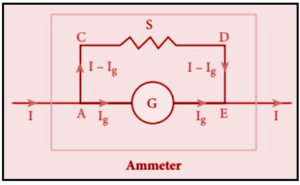
(1) Galvanometer to an Ammeter
An ammeter is a device that measures the amount of current flowing through an electrical circuit. The ammeter must have a low resistance so that the current travelling through it is unaffected. To measure the circuit current, an ammeter is connected in series.
By connecting a very low resistance in parallel with a galvanometer, it can be transformed into an ammeter. Shunt resistance S is the name for this low resistance. The scale is now calibrated in amperes, and the ammeter’s range is determined by the shunt resistance values.
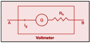
(2) Galvanometer to Voltmeter
A voltmeter is a device that measures the difference in potential between two locations in an electrical circuit. Otherwise, the value of the potential difference to be measured will change if it draws current from the circuit.
The voltmeter must have high resistance, and when connected in parallel, it will not draw any current, indicating the exact potential difference.
By connecting a high resistance Rh in series with a galvanometer, it can be transformed into a voltmeter. The scale is now calibrated in volts, and the voltmeter’s range is determined by the resistance values linked in series, that is, the resistance value is adjusted to the point where only current Ig causes a full-scale deflection in the galvanometer.


Difference between Ammeter and Voltmeter:
The ammeter and voltmeter are used to measure current flow and voltage measurement, respectively. The only distinction between these two gadgets is how they are used. To learn the difference between an ammeter and a voltmeter, look at the table below.
| Ammeter | Voltmeter | |
| Use | This device can be used to measure current flow. | This device measures the voltage or potential between two locations in an electric circuit. |
| Connection | An ammeter is linked in series with the electrical circuit element. | A voltmeter is used to connect the electrical circuit element in parallel mode. |
| Resistance | Even though it is not technically possible, an ideal Ammeter should have 0% resistance. | Voltmeters have a high resistance since they are used to measure the difference in potential between two terminals. |
| Accuracy | It correctly measures the current flow. | With the measurement, it is less precise. |
| Representation | The letter ‘A’ stands for Ammeter. | The letter ‘V’ stands for Voltmeter. |
Also read: Important Topic of Physics: Faraday’s Law
Frequently Asked Question FAQs:
Question 1: How to connect an ammeter and voltmeter in a circuit?
Answer: The ammeter is connected in series with the circuit element, whereas the voltmeter is connected in parallel with it. Both are employed as measuring instruments for electrical calculations, and they can assist in a variety of calculations by determining the current and voltage values in a circuit. Students can visualize how the entire setup is done using circuit diagrams. They show the correct approach to link these two electrical instruments in a circuit diagrammatically. A galvanometer and a potentiometer can also be used.
Question 2: Why does the ammeter connected in series?
Answer: To achieve the maximum current flow in the electric circuit, an ammeter is connected in series. Because of its low internal resistance, this is achievable. As a result, the current flow in the circuit may be precisely measured. In a circuit, objects connected in series experience the same current flow.
Question 3: Why do we connect the voltmeter in parallel?
Answer: We’ve already talked about why and how an ammeter is wired in series in a circuit. However, the voltmeter is being connected in parallel. The potential difference between the two sites will be zero if the voltmeter is connected in series with the circuit element because they are on the same line. The voltmeter’s high internal resistance is also used to calculate the potential difference between the two points.
Question 4: What is a digital voltmeter?
Answer: We’re all aware that there are several varieties of voltmeters on the market, each of which is utilized for a distinct purpose. The digital voltmeter is one such type of voltmeter. Instruments that detect the electrical potential difference between two points in a circuit are known as digital voltmeters. A circuit’s current can be either alternating current or direct current. In a digital voltmeter, there are five functioning segments. Pulse production, gating, counting clock pulses, analogue to digital conversion, and other operations are performed by these components.
