- Important Concepts in Alternating Current One Must Know Before Solving Numericals
- Chapter 7 Weightage in CBSE Physics
- NCERT Class 12 Physics Chapter 7: All Exercises
- NCERT Solutions For Alternating Current with Step-by-Step Solutions
- Additional Practice Questions
- Key Features of These NCERT Solutions
- Why Use Infinity Learn for Class 12 Physics NCERT Solutions?
- FAQs: NCERT Solutions For Class 12 Physics Alternating Current
NCERT Solutions For Class 12 Physics Chapter 7 – Alternating Current
By Rohit RP
|
Updated on 28 Oct 2026, 12:52 IST
Finding AC circuit problems difficult to solve? Chapter 7, Alternating Current, includes several concepts and formulas that can be confusing when you are solving questions on your own. RMS and peak values, reactance, impedance, resonance, power and transformers all require you to apply the right formula and follow the correct steps.
These NCERT Solutions for Class 12 Physics Chapter 7 explain the chapter-end questions step by step. The solutions show the relevant formula, substitution and calculation, along with a simple explanation wherever needed. This makes it easier to check your answers, understand the steps involved and revise the chapter.
You can also download the NCERT Solutions for Class 12 Physics Chapter 7 PDF for revision and offline study.
Important Concepts in Alternating Current One Must Know Before Solving Numericals
Chapter 7, Alternating Current, builds on the ideas introduced in Chapter 6: Electromagnetic Induction. The concepts of changing magnetic fields, induced emf and inductance help you understand how alternating current is produced and how AC circuits work.
Chapter 7 also connects with Chapter 8: Electromagnetic Waves. Both chapters deal with quantities that change with time. Concepts such as phase and phase difference used in AC circuits are also useful when studying changing electric and magnetic fields in electromagnetic waves.
What is Alternating Voltage and Current
An alternating voltage changes its magnitude and direction periodically with time. A sinusoidal AC voltage can be written as:
v = Vm sin ωt
where Vm is the peak voltage and ω is the angular frequency.

The corresponding current is also periodic. NCERT introduces AC because electrical mains supplies use alternating voltage and because AC voltage can be changed from one value to another using transformers.
What are RMS and Peak Values
The RMS value is the effective value of an AC voltage or current.
Best Courses for You

JEE

NEET

Foundation JEE

Foundation NEET

CBSE
Vrms = Vm/√2
Irms = Im/√2
Therefore,
Vm = √2 Vrms
Im = √2 Irms
For example, if the RMS voltage is 220 V, the peak voltage is approximately 311 V.
AC Through a Resistor
For a pure resistor, current and voltage are in phase.
I = V/R
The average power consumed is:
P = VI = I2R = V2/R
The RMS values of voltage and current are normally used in these calculations.
AC Through an Inductor
An inductor opposes changes in current through inductive reactance:
XL = ωL = 2πfL
For a pure inductor, current lags the voltage by 90°. Its average power consumption over a complete cycle is zero.
AC Through a Capacitor
The capacitive reactance is:
XC = 1/ωC
For a pure capacitor, current leads the voltage by 90°. Its average power consumption over a complete cycle is also zero.
Phasors
Phasors are rotating vectors used to represent the phase relationship between AC voltage and current. They make it easier to combine quantities that are not in phase.
Series LCR Circuit and Impedance
For a series LCR circuit:
Z = √[R2 + (XL − XC)2]
The current is:
I = V/Z
where V and I are RMS values when the supply voltage is given as an RMS value and Z is the impedance of the circuit.
Resonance
Resonance occurs in a series LCR circuit when:
XL = XC
Therefore,
ω0 = 1/√LC
At resonance, the impedance becomes minimum:
Z = R
and the current reaches its maximum value. Both the inductor and capacitor must be present for resonance to occur.
Power Factor and Wattless Current
The average power consumed by an AC circuit is:
P = VI cos φ
where cos φ is the power factor.
In a pure inductive or pure capacitive circuit, the phase difference is 90°. Therefore:
cos 90° = 0
and:
P = 0
The current flowing in such a circuit is called wattless current because it flows without average power being dissipated.
Transformer
A transformer works on the principle of mutual induction. It has primary and secondary coils wound around a soft-iron core. An alternating current in the primary produces changing magnetic flux, which induces an emf in the secondary.
For an ideal transformer:
Vs/Vp = Ns/Np
A transformer with more turns in the secondary is a step-up transformer, while one with fewer secondary turns is a step-down transformer.
Chapter 7 Weightage in CBSE Physics
For the 2026–27 CBSE Class 12 Physics syllabus, Chapter 7 is included in Unit IV: Electromagnetic Induction and Alternating Currents, which contains Chapters 6 and 7 and carries 18 marks in total. CBSE does not assign a separate fixed mark allocation to Chapter 7 alone.
NCERT Class 12 Physics Chapter 7: All Exercises
The exercises cover important numerical and conceptual questions based on RMS values, inductive and capacitive reactance, AC power, LC oscillations, series LCR resonance and transformers.
Note: As per the current rationalized NCERT syllabus, the earlier "Additional Exercises" set for this chapter has been removed.
Key Formulas for Chapter 7
| Concept | Formula |
| RMS voltage | V = Vm/√2 |
| RMS current | I = Im/√2 |
| Inductive reactance | XL = ωL = 2πfL |
| Capacitive reactance | XC = 1/ωC |
| LCR impedance | Z = √[R2 + (XL − XC)2] |
| AC current | I = V/Z |
| Resonant angular frequency | ω0 = 1/√LC |
| Resonant frequency | f0 = 1/(2π√LC) |
| AC power | P = VI cos φ |
| Transformer voltage ratio | Vs/Vp = Ns/Np |
NCERT Solutions For Alternating Current with Step-by-Step Solutions
- A 100 Ω resistor is connected to a 220 V, 50 Hz ac supply.
- (a) What is the rms value of current in the circuit?
- (b) What is the net power consumed over a full cycle?
Solution
(a) RMS current
Given: R = 100 Ω, V = 220 V
For a resistor:
I = V/R
Substitute the values:
I = 220/100 = 2.2 A
| Irms = 2.2 A |
(b) Net power consumed
For a pure resistor:
P = VI
P = 220 × 2.2 = 484 W
| P = 484 W |
The resistor consumes electrical energy as heat, so its average power consumption is not zero.
- (a) The peak voltage of an ac supply is 300 V. What is the rms voltage?
(b) The rms value of current in an ac circuit is 10 A. What is the peak current?
Solution
(a) RMS voltage
Given: Vm = 300 V
The relation between peak and RMS voltage is:
V = Vm/√2
V = 300/√2 ≈ 212.1 V
| Vrms ≈ 212.1 V |
(b) Peak current
Given: I = 10 A
Im = √2 I
Im = √2 × 10 ≈ 14.14 A
| Im ≈ 14.14 A |
- A 44 mH inductor is connected to 220 V, 50 Hz ac supply. Determine the rms value of the current in the circuit.
Solution
Given: L = 44 mH = 44 × 10−3 H, V = 220 V, f = 50 Hz
Step 1: Find inductive reactance
XL = 2πfL
XL = 2π(50)(44 × 10−3) ≈ 13.82 Ω
Step 2: Find RMS current
For a pure inductor:
I = V/XL
I = 220/13.82 ≈ 15.9 A
| Irms ≈ 15.9 A |
The inductor limits the AC current through its inductive reactance rather than ordinary resistance.
- A 60 μF capacitor is connected to a 110 V, 60 Hz ac supply. Determine the rms value of the current in the circuit.
Solution
Given: C = 60 μF = 60 × 10−6 F, V = 110 V, f = 60 Hz
Step 1: Find capacitive reactance
XC = 1/(2πfC)
XC = 1/(2π(60)(60 × 10−6)) ≈ 44.21 Ω
Step 2: Find RMS current
For a pure capacitor:
I = V/XC
I = 110/44.21 ≈ 2.49 A
| Irms ≈ 2.49 A |
- In Exercises 7.3 and 7.4, what is the net power absorbed by each circuit over a complete cycle. Explain your answer.
Solution
Exercise 7.3 contains a pure inductor, while Exercise 7.4 contains a pure capacitor.
For the inductor
In a pure inductive circuit, current lags voltage by 90°. Therefore φ = 90°. The average power is P = VI cos φ, so P = VI cos 90° = 0.
For the capacitor
In a pure capacitive circuit, current leads voltage by 90°. Again, P = VI cos 90° = 0.
| Pinductor = 0 W Pcapacitor = 0 W |
Why?
The inductor and capacitor can exchange energy with the AC source during a cycle, but they do not dissipate net energy over a complete cycle. NCERT therefore describes the current in such circuits as wattless current.
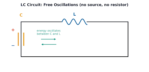
- A charged 30 μF capacitor is connected to a 27 mH inductor. What is the angular frequency of free oscillations of the circuit?
Solution
Given: C = 30 μF = 30 × 10−6 F, L = 27 mH = 27 × 10−3 H
For an LC circuit:
ω0 = 1/√LC
Step 1: Calculate LC
LC = (27 × 10−3)(30 × 10−6) = 810 × 10−9 = 8.10 × 10⁻⁷
Step 2: Calculate angular frequency
ω0 = 1/√(8.10 × 10−7) ≈ 1.11 × 10³ rad s−1
| ω0 ≈ 1.11 × 10³ rad s−1 |
The capacitor and inductor exchange energy between electric and magnetic forms, producing free oscillations.
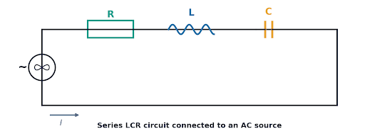
- A series LCR circuit with R = 20 Ω, L = 1.5 H and C = 35 μF is connected to a variable-frequency 200 V ac supply. When the frequency of the supply equals the natural frequency of the circuit, what is the average power transferred to the circuit in one complete cycle?
Solution
Given: R = 20 Ω, L = 1.5 H, C = 35 μF, V = 200 V
The supply frequency is equal to the natural frequency, so the circuit is at resonance.
Step 1: Use the resonance condition
At resonance:
XL = XC
Therefore, the reactive components cancel each other. Hence:
Z = R = 20 Ω
Step 2: Find RMS current
I = V/Z = 200/20 = 10 A
Step 3: Find average power
At resonance, φ = 0. Therefore:
P = VI cos φ = (200)(10) cos 0° = 2000 W
Alternatively: P = I2R = (10)2(20) = 2000 W
| P = 2000 W = 2.0 kW |
At resonance, the impedance is minimum and the power factor is 1, so the power transferred to the resistive part of the circuit is maximum.
- Figure 7.17 shows a series LCR circuit connected to a variable frequency 230 V source. L = 5.0 H, C = 80 μF, R = 40 Ω.
- (a) Determine the source frequency which drives the circuit in resonance.
- (b) Obtain the impedance of the circuit and the amplitude of current at the resonating frequency.
- (c) Determine the rms potential drops across the three elements of the circuit. Show that the potential drop across the LC combination is zero at the resonating frequency.
Solution
Given: L = 5.0 H, C = 80 μF = 80 × 10−6 F, R = 40 Ω, V = 230 V
(a) Resonant frequency
The resonant angular frequency is:
ω0 = 1/√LC
ω0 = 1/√[(5.0)(80 × 10−6)] = 50 rad s−1
Convert angular frequency to frequency:
f0 = ω0/2π = 50/2π ≈ 7.96 Hz
| f0 ≈ 7.96 Hz |
(b) Impedance and amplitude of current
At resonance:
XL = XC ⇒ Z = R = 40 Ω
The given 230 V is an RMS value. First find the RMS current:
I = V/Z = 230/40 = 5.75 A
The question asks for the amplitude of current, so:
Im = √2 I = √2(5.75) ≈ 8.13 A
| Z = 40 Ω Im ≈ 8.13 A |
(c) RMS potential drops
First calculate the reactances at resonance:
XL = ω0L = (50)(5) = 250 Ω XC = XL = 250 Ω
VR = IR = (5.75)(40) = 230 V
VL = IXL = (5.75)(250) = 1437.5 V
VC = IXC = (5.75)(250) = 1437.5 V
| VR = 230 V VL = 1437.5 V VC = 1437.5 V |
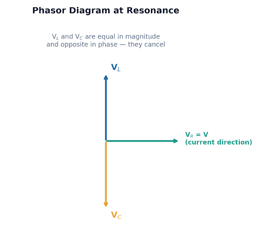
At resonance, VL and VC are equal and opposite — they cancel, leaving VR equal to the supply voltage
Why is the LC potential drop zero?
The voltages across the inductor and capacitor are equal in magnitude but opposite in phase at resonance. Therefore:
VLC = VL − VC = 1437.5 − 1437.5
| VLC = 0 V |
This does not mean that the individual voltages across the inductor and capacitor are zero. They are both large, but they cancel each other because they are 180° apart in their phasor contribution. NCERT specifically notes that the voltages across L and C cancel at resonance.
Additional Practice Questions
The following two questions are not from NCERT. They are included to bring the total to 10 questions and cover important Chapter 7 concepts that are not tested directly by the eight current chapter-end exercises.
- Additional Practice Question: A step-down transformer has 500 turns in its primary coil and 100 turns in its secondary coil. The primary is connected to a 250 V AC supply. The secondary supplies 2 A at 50 V. If the transformer is 80% efficient, determine the input current.
Solution
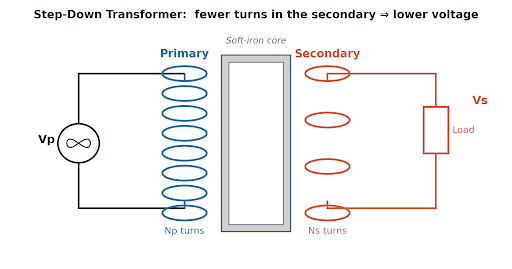
A step-down transformer: fewer secondary turns give a lower secondary voltage
Step 1: Identify the transformer
Given: Np = 500, Ns = 100
Since Ns < Np, the transformer is a step-down transformer.
Step 2: Find the secondary voltage
For an ideal transformer:
Vs/Vp = Ns/Np
Vs = Vp(Ns/Np) = 250 × (100/500) = 50 V
So the given secondary voltage is consistent with the turns ratio.
Step 3: Calculate output power
Pout = VsIs = 50 × 2 = 100 W
Step 4: Use transformer efficiency
Given: η = 80%
η = (Pout/Pin) × 100
0.80 = 100/Pin ⇒ Pin = 100/0.80 = 125 W
Step 5: Find input current
Pin = VpIp ⇒ Ip = Pin/Vp = 125/250 = 0.5 A
| Ip = 0.5 A |
The secondary has fewer turns, so the transformer reduces voltage. In an actual transformer, some energy is lost through effects such as flux leakage, winding resistance, eddy currents and hysteresis.
- Additional Practice Question: A pure inductive AC circuit is connected to a 220 V supply and carries an rms current of 5 A. Find the average power consumed by the circuit over one complete cycle. Explain why the current is called wattless current.
Solution
Given: V = 220 V, I = 5 A
For a pure inductor, current lags voltage by 90°. Therefore φ = 90°.
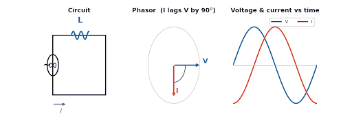
In a pure inductor, current and voltage are 90° out of phase
Step 1: Use the AC power formula
P = VI cos φ
P = (220)(5) cos 90°
Since cos 90° = 0, we get:
P = 0 W
| P = 0 W |
Why is it called wattless current?
Current is still flowing through the inductor, but the average power consumed over a complete cycle is zero. The current is therefore called wattless current. NCERT defines the current in a purely inductive or capacitive circuit this way because the phase difference is 90° and the power factor is zero.
How to Approach Alternating Current Numericals
Before substituting values, identify which component or circuit is involved.
For a resistor
Use: I = V/R and P = VI
For an inductor
First calculate: XL = 2πfL. Then: I = V/XL
For a capacitor
First calculate: XC = 1/(2πfC). Then: I = V/XC
For a series LCR circuit
Calculate XL = 2πfL and XC = 1/(2πfC). Then Z = √[R2 + (XL − XC)2] and I = V/Z.
If the circuit is at resonance
Immediately use XL = XC, therefore Z = R. This can considerably shorten the calculation.
Key Features of These NCERT Solutions
- Step-by-step solutions for the questions in the chapter
- Clear explanations of formulas and calculations used in each solution
- Solved problems on AC circuits, reactance, resonance, power and transformers
- NCERT-based practice with additional questions on important chapter topics
- Exam-ready answers that show the required formulas, calculations and final answers
- Free access to the solutions and related study resources
Why Use Infinity Learn for Class 12 Physics NCERT Solutions?
Infinity Learn provides chapter-wise NCERT Solutions for Class 12 Physics with step-by-step explanations designed to make numerical and conceptual questions easier to follow.
Students can use the solutions alongside the NCERT textbook: first attempt the question independently, then compare the method, calculation and final answer with the solution.
Infinity Learn also provides other Class 12 learning resources, including NCERT solutions, practice material and courses for board and competitive exam preparation.
course
No courses found
FAQs: NCERT Solutions For Class 12 Physics Alternating Current
What is the difference between RMS and peak value of AC?
The peak value is the maximum instantaneous value reached by an AC voltage or current. RMS is its effective value, given by Vrms = Vm/√2 and Irms = Im/√2. For a sinusoidal AC supply, the RMS value is approximately 0.707 times the peak value.
How do I calculate impedance in a series LCR circuit?
First calculate the inductive and capacitive reactances, XL = 2πfL and XC = 1/(2πfC). Then use Z = √[R2 + (XL − XC)2]. The RMS current can then be found using I = V/Z.
What is resonance in an AC circuit?
Resonance in a series LCR circuit occurs when XL = XC. At this point ω0 = 1/√LC, and the impedance becomes equal to the resistance, Z = R. The current therefore reaches its maximum value.
What is wattless current?
Wattless current is the current flowing in a purely inductive or capacitive circuit where the average power consumed over a complete cycle is zero. The phase difference between voltage and current is 90°, so the power factor is zero.
How does a transformer work?
A transformer works on the principle of mutual induction. An alternating current in the primary coil produces changing magnetic flux, which induces an emf in the secondary coil. The voltage ratio depends on the ratio of secondary to primary turns: Vs/Vp = Ns/Np.
What determines transformer efficiency?
Transformer efficiency is determined by how much of the input power reaches the secondary rather than being lost to winding resistance, eddy currents, hysteresis and flux leakage in the core. Well-designed transformers can exceed 95% efficiency, while smaller or older ones, like the one in Q9, can be considerably less efficient.
