- Download Complete NCERT Solutions for Class 12 Physics Chapter 3 – Current Electricity
- NCERT Solutions for Class 12 Physics Chapter 3 – Current Electricity
- NCERT Solutions for Class 12 Physics Chapter 3: Important Questions
- Key Features of NCERT Solutions for Class 12 Physics Chapter 3 Current Electricity
- Why Infinity Learn NCERT Solutions for Class 12 Physics Chapter 3 Current Electricity?
- Prepare Current Electricity with NCERT Solutions
- FAQs: NCERT Solutions for Class 12 Current Electricity
NCERT Solutions for Class 12 Physics Chapter 3 — Current Electricity
By Rohit RP
|
Updated on 28 Oct 2026, 10:58 IST
Current Electricity is an important chapter in Class 12 Physics that explains how electric charge flows through conductors and how different electrical components behave in a circuit. The chapter introduces concepts such as electric current, drift velocity, resistance, resistivity, cells, Kirchhoff's laws, Wheatstone bridge, meter bridge and potentiometer.
The chapter combines theoretical concepts with numerical problems, making a clear understanding of the formulas and their applications essential for solving questions effectively. These NCERT Solutions for Class 12 Physics Chapter 3 – Current Electricity provide step-by-step explanations for selected NCERT exercises, helping students understand the methods used to arrive at each answer.
The solutions are also useful for students preparing for CBSE examinations and entrance examinations such as JEE Main and NEET, where concepts related to current, resistance and electrical circuits are frequently applied.
Download Complete NCERT Solutions for Class 12 Physics Chapter 3 – Current Electricity
Download the NCERT Solutions for Class 12 Physics Chapter 3 – Current Electricity PDF to revise the chapter and practise the questions at your convenience.
Key Concepts Covered in Class 12 Physics Chapter 3
Before solving numerical problems, students should be familiar with the following concepts from Current Electricity:
- Electric current and current density
- Drift velocity of electrons
- Relation between current and drift velocity
- Ohm's law
- Resistance and resistivity
- Conductivity
- Dependence of resistance on temperature
- Combination of resistors in series and parallel
- EMF and internal resistance of a cell
- Combination of cells
- Kirchhoff's junction and loop rules
- Wheatstone bridge
- Meter bridge
- Potentiometer
- Measurement of potential difference and EMF
NCERT Solutions for Class 12 Physics Chapter 3 – Current Electricity
Chapter Overview
Current Electricity deals with the movement of electric charges through conducting materials. Unlike electrostatics, where charges are considered at rest, this chapter focuses on situations in which charges move through a conductor under the influence of an electric field.
Some of the important relationships introduced in the chapter include:
Electric current

I = Q⁄t
where (Q) is the charge flowing through a conductor in time (t).
Best Courses for You

JEE

NEET

Foundation JEE

Foundation NEET

CBSE
Current in terms of drift velocity
I = neAvd
where:
- n = number density of free electrons
- e = magnitude of electronic charge
- A = area of cross-section of the conductor
- vd = drift velocity
Ohm's law
V = IR
Resistance of a uniform conductor
R = ρl⁄A
where:
- ρ = resistivity
- l = length of the conductor
- A = area of cross-section
Resistors in series
Rs = R1 + R2 + R3 + …
Resistors in parallel
1⁄Rp = 1⁄R1 + 1⁄R2 + 1⁄R3 + …
Terminal voltage of a cell during discharge
V = ε − Ir
where:
- ε = EMF of the cell
- r = internal resistance
- I = current
Terminal voltage during charging
V = ε + Ir
Wheatstone bridge balance condition
P⁄Q = R⁄S
Potentiometer relation
E1⁄E2 = l1⁄l2
These formulas should be used together with the conditions given in each question rather than memorised in isolation.
NCERT Solutions for Class 12 Physics Chapter 3: Important Questions
Question 1: The storage battery of a car has an emf of 12 V. If the internal resistance of the battery is 0.4 Ω, what is the maximum current that can be drawn from the battery?
Given:
EMF of the battery, ε = 12 V
Internal resistance, r = 0.4 Ω
For maximum current, the external resistance is zero.
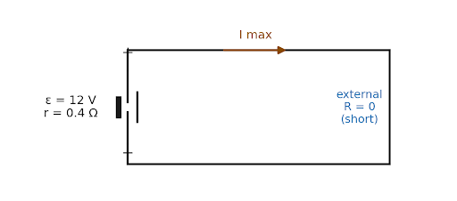
Therefore,
Imax = ε⁄r
Imax = 12⁄0.4
Imax = 30 A
Answer:
The maximum current that can be drawn from the battery is 30 A.
Question 2: A battery of emf 10 V and internal resistance 3 Ω is connected to a resistor. If the current in the circuit is 0.5 A, what is the resistance of the resistor? What is the terminal voltage of the battery when the circuit is closed?
Given:
EMF, ε = 10 V
Internal resistance, r = 3 Ω
Current, I = 0.5 A
Let the resistance of the external resistor be (R).
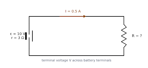
Using the relation:
ε = I(R + r)
10 = 0.5(R + 3)
20 = R + 3
Therefore,
R = 17 Ω
Terminal voltage
The terminal voltage of a discharging cell is:
V = ε − Ir
Substituting the values:
V = 10 − (0.5 × 3)
V = 10 − 1.5
V = 8.5 V
Answer:
Resistance of the resistor = 17 Ω
Terminal voltage of the battery = 8.5 V
Question 3: At room temperature (27.0 °C) the resistance of a heating element is 100 Ω. What is the temperature of the element if the resistance is found to be 117 Ω, given that the temperature coefficient of the material of the resistor is 1.70 × 10⁻⁴ °C⁻¹.
Given:
Initial resistance, R1 = 100 Ω
Initial temperature, T1 = 27 °C
Final resistance, R2 = 117 Ω
Temperature coefficient, α = 1.70×10⁻⁴ °C-1
The temperature dependence of resistance is given by:
R2 = R1[1 + α(T2 − T1)]
Substituting the values:
117 = 100[1 + 1.70×10⁻⁴(T2 − 27)]
Therefore,
1.17 = 1 + 1.70×10⁻⁴(T2 − 27)
0.17 = 1.70×10⁻⁴(T2 − 27)
T2 − 27 = 0.17⁄(1.70×10⁻⁴)
T2 − 27 = 1000
Therefore,
T2 = 1027 °C
Answer:
The temperature of the heating element is 1027 °C.
Question 4: A negligibly small current is passed through a wire of length 15 m and uniform cross-section 6.0 × 10⁻⁷ m², and its resistance is measured to be 5.0 Ω. What is the resistivity of the material at the temperature of the experiment?
Given:
Length of wire, l = 15 m
Area of cross-section, A = 6.0×10⁻⁷ m2
Resistance, R = 5.0 Ω
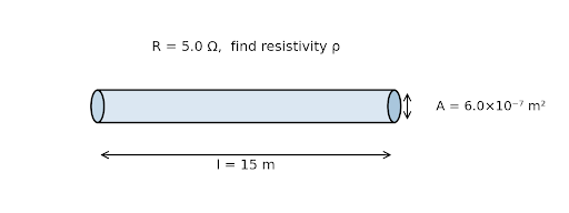
The resistance of a uniform conductor is:
R = ρl⁄A
Therefore,
ρ = RA⁄l
Substituting the values:
ρ = (5.0 × 6.0×10-7)⁄15
ρ = 30×10-7⁄15
ρ = 2.0×10⁻⁷ Ω·m
Answer:
The resistivity of the material is 2.0 × 10⁻⁷ Ω·m.
Question 5: A silver wire has a resistance of 2.1 Ω at 27.5 °C, and a resistance of 2.7 Ω at 100 °C. Determine the temperature coefficient of resistivity of silver.
Given:
R1 = 2.1 Ω, T1 = 27.5 °C
R2 = 2.7 Ω, T2 = 100 °C
For a conductor,
R2 = R1[1 + α(T2 − T1)]
Therefore,
α = (R2 − R1) ⁄ [R1(T2 − T1)]
Substituting the values:
α = (2.7 − 2.1) ⁄ [2.1(100 − 27.5)]
α = 0.6 ⁄ (2.1 × 72.5)
α = 0.6⁄152.25
α ≈ 3.94×10⁻³ °C-1
Answer:
The temperature coefficient of resistivity of silver is approximately 3.94 × 10⁻³ °C⁻¹.
Question 6: Determine the current in each branch of the network shown in Fig. 3.30.
This question requires the circuit shown in Fig. 3.30 to establish the directions and values of the branch currents.
Applying Kirchhoff's junction rule and Kirchhoff's loop rule to the network gives the required simultaneous equations.
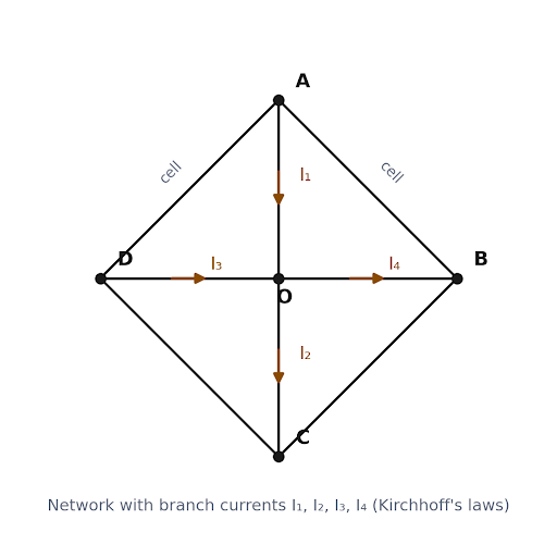
Figure 3.30 (representative) — Network node layout showing the assumed branch-current directions I₁, I₂, I₃, I₄ used in applying Kirchhoff's laws.
For the circuit, the branch currents can be obtained as:
I1 = 10⁄17 A
I2 = 4⁄17 A
I3 = 6⁄17 A
I4 = −2⁄17 A
The negative sign indicates that the actual direction of that branch current is opposite to the direction initially assumed.
Thus, the magnitudes of the relevant branch currents are approximately:
10⁄17 A ≈ 0.588 A
4⁄17 A ≈ 0.235 A
6⁄17 A ≈ 0.353 A
2⁄17 A ≈ 0.118 A
Answer:
The current in each branch is obtained by simultaneously applying Kirchhoff's junction and loop rules. The negative value for a calculated current indicates that its actual direction is opposite to the assumed direction.
Note: The figure should be retained alongside this question on the webpage because the branch-current directions depend on the circuit shown in Fig. 3.30. (For developers)
Question 7
In a meter bridge [Fig. 3.27], the balance point is found to be at 39.5 cm from the end A, when the resistor S is of 12.5 Ω. Determine the resistance of R. Why are the connections between resistors in a Wheatstone or meter bridge made of thick copper strips?
Given:
Balance point, l = 39.5 cm
Resistance, S = 12.5 Ω
Length of bridge wire, 100 cm
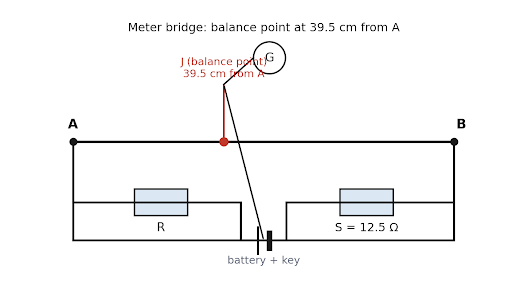
At balance:
R⁄S = (100 − l)⁄l
Therefore,
R⁄12.5 = (100 − 39.5)⁄39.5
R⁄12.5 = 60.5⁄39.5
R = 12.5 × 60.5⁄39.5
R ≈ 19.1 Ω
Why are thick copper strips used?
The connections are made using thick copper strips because copper has very low resistivity and thick strips have very low resistance. This makes the resistance of the connecting wires negligible compared with the resistors being measured.
Answer:
The resistance of R is approximately 19.1 Ω.
Thick copper strips are used to minimise the resistance of the connections.
Question 7 – Part (b): Determine the balance point of the bridge above if R and S are interchanged.
Initially, the balance point is:
l = 39.5 cm
On interchanging R and S, the resistance ratio is inverted. Therefore, the new balance length is:
l′ = 100 − 39.5
l′ = 60.5 cm
Answer:
The new balance point is 60.5 cm from end A.
Question 7 – Part ©: What happens if the galvanometer and cell are interchanged at the balance point of the bridge? Would the galvanometer show any current?
Solution: At the balance point, the two points connected to the galvanometer are at the same potential.
Therefore, there is no potential difference across the galvanometer.
Interchanging the positions of the galvanometer and cell does not change this balance condition.
Answer:
The galvanometer would not show any current because the potential difference across it remains zero at the balance point.
Question 8: In a potentiometer arrangement, a cell of emf 1.25 V gives a balance point at 35.0 cm length of the wire. If the cell is replaced by another cell and the balance point shifts to 63.0 cm, what is the emf of the second cell?
Given:
EMF of first cell, E1 = 1.25 V
Balance length for first cell, l1 = 35.0 cm
Balance length for second cell, l2 = 63.0 cm
Let the EMF of the second cell be (E₂).
Figure 3.8 — Potentiometer wire AB with balance lengths l₁ and l₂ for the two cells E₁ and E₂.
For a potentiometer under the same conditions:
E1⁄E2 = l1⁄l2
Therefore,
E2 = E1 × l2⁄l1
E2 = 1.25 × 63⁄35
E2 = 1.25 × 1.8
E2 = 2.25 V
Answer:
The EMF of the second cell is 2.25 V.
Kirchhoff's junction rule: Sum of currents entering a junction = Sum of currents leaving the junction.
Key Features of NCERT Solutions for Class 12 Physics Chapter 3 Current Electricity
- Step-by-step explanations: Follow each numerical from the given information and relevant formula through to the final answer.
- Simple, easy-to-understand methods: Understand how to approach circuit problems, including questions involving Kirchhoff's laws and combinations of resistors.
- Exam-oriented answers: Solutions are presented in a structured format that makes the working and final answer easy to follow.
- Expert-verified solutions: Include this only if Infinity Learn can substantiate the claim editorially.
- Useful for CBSE and JEE/NEET preparation: Build the core concepts needed for board-level questions while strengthening the fundamentals used in competitive-exam preparation.
- Free access to solutions and additional resources: Students can use the solutions alongside other available Infinity Learn learning resources.
Why Infinity Learn NCERT Solutions for Class 12 Physics Chapter 3 Current Electricity?
- Clear explanation of Ohm's law and resistivity: Understand the relationship between potential difference, current and resistance through solved problems.
- In-depth coverage of Kirchhoff's laws and circuit combinations: Work through multi-loop circuits and different resistor arrangements systematically.
- Simplified approach to Wheatstone bridge and potentiometer problems: Identify the relevant relationships and follow the calculation step by step.
- Structured connection between theory and numerical circuit analysis: See how concepts such as drift velocity, resistivity, emf and internal resistance are applied in numerical questions.
- Solutions by expert Physics educators: Include this only if it is an approved, verifiable claim.
- Updated for the applicable syllabus: Keep the content aligned with the latest NCERT and CBSE requirements.
- Additional learning support: Students can continue with relevant Infinity Learn video lessons and practice resources available through the web and app.
Prepare Current Electricity with NCERT Solutions
Current Electricity becomes considerably easier once the relationship between current, resistance, potential difference and circuit configuration is clear. Regular practice is particularly important for questions involving Kirchhoff's laws, bridge circuits and potentiometers because these require students to apply concepts rather than simply substitute values into a formula.
Use these NCERT Solutions for Class 12 Physics Chapter 3 – Current Electricity alongside the textbook, work through the exercises yourself and use the worked solutions to verify your approach.
course
No courses found
FAQs: NCERT Solutions for Class 12 Current Electricity
How do I use Kirchhoff's laws to solve circuit problems?
Start by assigning assumed current directions to the different branches of the circuit. Apply Kirchhoff's junction rule at suitable junctions and Kirchhoff's loop rule to independent closed loops. The resulting simultaneous equations can then be solved to determine the branch currents. If a calculated current is negative, its actual direction is opposite to the assumed direction.
What is the Wheatstone bridge principle?
A Wheatstone bridge works on the principle of balancing two potential-divider arms. At balance, no current flows through the galvanometer because the two points connected to it are at the same potential.
The balance condition is:
P⁄Q = R⁄S
How do I calculate drift velocity of electrons?
Drift velocity can be calculated using:
I = neAvd
Therefore,
vd = I⁄(neA)
where (I) is current, (n) is the number density of free electrons, (e) is electronic charge and (A) is the cross-sectional area of the conductor.
What is the difference between EMF and terminal voltage?
EMF is the energy supplied by a cell per unit charge and is equal to the potential difference across its terminals when no current is being drawn. When the cell supplies current, some potential is lost across its internal resistance, so the terminal voltage becomes:
V = ε − Ir
How does a potentiometer measure unknown EMF?
A potentiometer compares the unknown EMF with a known potential difference. At the balance point, no current is drawn from the cell being measured. For two cells under the same potentiometer conditions:
E1⁄E2 = l1⁄l2
where (l₁) and (l₂) are their respective balance lengths.
How many exercises are there in NCERT Class 12 Physics Chapter 3?
The current NCERT Chapter 3 contains 23 numbered exercises, from Exercise 3.1 to Exercise 3.23. Exercises 3.14 to 3.23 are given under the Additional Exercises section.
