
Table of Contents
Introduction:
When an electric modern-day flows through a bulb or any conductor, the conductor offers some obstruction to the current and this obstruction is known as electric resistance and is denoted by means of r. Each cloth has an electrical resistance and that is the purpose why conductors give out warmth while cutting-edge passes via it.
Electrical resistance is a degree of opposition that a circuit gives to the glide of electrical cutting-edge. You might examine it to the diameter of a hose. In reality, for metallic wire, that is a fantastic analogy: the small-diameter wire has high resistance (loads of opposition to modern-day flow), and the large-diameter twine has low resistance (no longer a good deal of opposition to electric currents). Of route, the type of metal makes a distinction too. Iron twine has better resistance for a given diameter than copper wire. Nichrome wire nevertheless has extra resistance.
What is Electrical Resistance?
In keeping with Ohm’s law, there’s a relation between the modern flowing through a conductor and the potential distinction throughout it. The electrical resistance of a circuit is dependent on the voltage applied and the current flowing through it. By way of example,
V ∝ I V = IR
Where,
V is The potential difference across the conductor is measured in volts
I is The current flowing through the conductor (in amps)
R is Resistance (in ohms) is the constant of proportionality
As a result of rearranging the above relationship,
R = VI
The unit of electrical resistance is ohms.
1 ohm = 1 Volt/ 1 Ampere
Some materials conduct electricity more easily than others. This electrical resistance measures how much the flow of electricity is restricted within the circuit.


Factors Affecting Electrical Resistance of Conductor
Conducting wires are resistive due to the collision of free electrons drifting towards the positive end of the wire.
Resistances of materials, e.g. wires, conductors, are determined by the following factors:
- Length of the material
- Area of the material
- Temperature
- Resistance on Increasing or Decreasing the Length
Suppose there are two identical slabs of conductors, each having length ‘l’ and cross-sectional area ‘A’. We’ll use ‘V’ to represent the potential difference applied to either slab/conductor and ‘I’ to represent the current flowing through it.
So, the resistance of the conductor is:
R = V/I
With the two identical conductors side-by-side, the total length becomes l + l = 2l. In the case of the same potential difference between both slabs, the current equals I/2. This results in the following resistance:
R’ = V/I/2 = 2V/I = 2R…..(1)
The equation (1) states that as the length of a wire or conductor is doubled, the resistance also doubles, i.e., R ∝ I.
- Area of the Conductor
Consider a slab that can be cut into two halves of length ‘l’, and an area of ‘A/2’ on the cross-section. With a potential difference applied across the ends of a conductor and a current flowing through it of I/2, the resistance is:
R’ = V/I/2 = 2 V/I = 2R…..(2)
From equation (2), we can see that on dividing the conductor slab into halves, i.e., on halving the area of the cross-section of a conductor, the resistance doubles, resulting in R x 1/A.
Nature of the Material
- Conductors
Low resistance is a characteristic of conductors. It is important to note that copper has a very low resistance but a very high conductivity. That is the reason copper is used as a connecting wire. Silver and gold are also conductors of electricity.
If R is the resistance, then conductance ‘G’ is:
G = 1/R
- Insulators
Insulators offer very high resistance. There are semiconductors between the conductor and the insulator, which have very high resistance.
- Alloys
Alloys like Manganin and Constantan offer low resistance, and their smaller lengths are needed for wires of a given diameter in order to make standard resistance values.
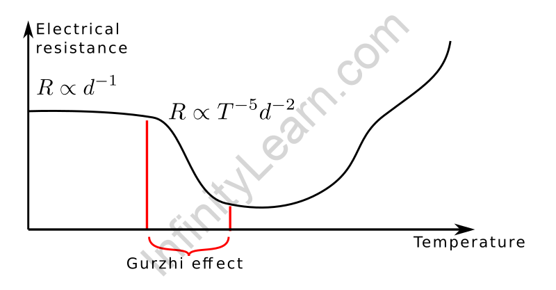
Temperature of the Material
When the temperature of a material rises, the thermal energy of the material also increases because of which atoms and ions in a conductor begin vibrating with higher amplitudes and frequencies.
Once the free electrons start drifting towards the positive end of the conductor, the relaxation time decreases. Thus, the resistance of the conductor increases.
If R0 was the resistance of the material at 0℃ and Rf is the current temperature, then the rise in resistance with the rise in the temperature by t℃ is given by:
Rf = R0 (1 + ∝t + βt2)
Here, ∝ & β refer to resistance at different temperatures, which varies from metal to metal. The unit of 1/K or 1/℃.
In practical applications, is given by:
∝ = increase in temperature/original resistance x rise in temperature
The temperature coefficient is defined as the increase in resistance per unit original resistance per degree rise in temperature.
The temperature is different for different temperatures. Now, if the temperature varies, i.e., if the temperature ranges from t1℃ to t2℃, then ∝ is:
∝ = Rf – R0/ R0×(t2-t1)


What Is Resistivity?
Electric powered resistivity is described as the electrical resistance supplied in step with unit duration and unit move-sectional vicinity at a selected temperature and is denoted with the aid of ρ. Electrical resistance is likewise known as specific electrical resistance. OHMs is the SI unit of electrical resistivity. Following is the components of electrical resistivity:
ρ = E J
Where,
- ρ is the resistivity of the material in Ω.m
- E is the electric field in V.m-1
- J is the current density in A.m-2
Difference between resistance and resistivity
Resistance is defined because the property of the conductor opposes the waft of electrical modern. It is also defined because of the ratio of the voltage implemented to the electrical current flowing through it.
The resistance of a conductor depends on the duration, location of the go-segment, and the character of the cloth that is used within the production of the conductor. For a conductor, the resistance is without delay proportional to the length of the conductor and inversely proportional to the place of pass-section. Resistivity is defined as the resistance presented by way of the fabric in step with the unit period for the unit cross-phase.
The SI unit of resistivity is the ohm. Metre. Resistivity increases linearly with temperature. The resistivity of conductors is low compared to the resistivity of the insulators. Therefore, it could be represented as:
Resistivity of conductors < Resistivity of alloys < Resistivity of insulators.
Also read: Important Topic of Physics: Power
FAQs
What is the reciprocal of resistivity?
Conductivity is the reciprocal of resistivity.
Name the materials having resistance almost equal to zero.
Superconductors.
