
Table of Contents
Introduction
A logic gate is either an idealized model of computation or a physical electronic device that performs a Boolean function, which is a logical operation performed on a single binary output from a set of binary inputs. Depending on the context, the term may refer to an ideal logic gate, such as one with zero rise time and unlimited fan-out, or to a non-ideal physical device. Logic gates are commonly constructed using electronic switches such as diodes or transistors, but they can also be constructed using vacuum tubes, electromagnetic relays (relay logic), fluidic logic, pneumatic logic, optics, molecules, or even mechanical parts. Amplification allows logic gates to be cascaded in the same manner that Boolean functions may, allowing a physical model of all of the Boolean logic, and thus all of the algorithms and mathematics that can be expressed using Boolean logic, to be built. Logic circuits include multiplexers, registers, arithmetic logic units (ALUs), and computer memory. More than 100 million gates can be found in a single CPU. MOSFETs (metal-oxide-semiconductor field-effect transistors) are used to make the majority of gates in modern practice. AND-OR-Invert (AOI) and OR-AND-Invert (OAI) compound logic gates are frequently used in circuit design because their construction using MOSFETs is simpler and more efficient than the sum of the individual gates. Logic gates in a circuit make decisions based on a combination of digital signals from their inputs. Logic gates typically have two inputs and one output. Boolean algebra is the foundation of logic gates. Every terminal is in one of two binary states at any given time: false or true. True represents 1 and falsely represents 0. The binary output will differ depending on the type of logic gate used and the combination of inputs. A logic gate can be compared to a light switch in that the output is off in one position — 0, and on in another — 1. Logic gates are frequently found in integrated circuits (IC).
Overview
The electrical conductivity of a semiconductor material is somewhere between that of a conductor, such as metallic copper, and that of an insulator, such as glass. Its resistivity decreases as the temperature rises, whereas metals have the opposite effect. The conductivity of a crystal structure can be improved by introducing impurities (doping) into it. A semiconductor junction is formed when two distinct doped regions in the same crystal exist. The behavior of charge carriers like electrons, ions, and electron holes at these junctions is the basis for diodes, transistors, and most modern electronics. Semiconductors include elements from the periodic table’s metalloid staircase, such as silicon, germanium, gallium arsenide, and gallium arsenide. Gallium arsenide is the second most common semiconductor after silicon, and it is used in laser diodes, solar cells, microwave-frequency integrated circuits, and other applications. Silicon is an important component in the production of nearly all electrical circuits.
In digital circuits, a logic gate is a simple switching circuit that determines whether an input pulse can pass through to the output. A digital circuit’s building blocks are logic gates, which perform the numerous logical operations required by any digital circuit. These can accept two or more inputs but only output one. The output of a logic gate is determined by the combination of inputs applied to it. To carry out logical processes, logic gates employ Boolean algebra. Logic gates can be found in almost every digital device we use on a daily basis. Our phones, laptops, tablets, and memory devices all use logic gates in their architecture. A logic gate is a device that serves as a foundation for digital circuits. They carry out basic logical functions that are essential in digital circuits. Logic gates are found in the majority of electronic devices we use today. Logic gates, for example, can be found in technologies such as smartphones, tablets, and memory devices.


Universal logic gates
Individual logic gates can be linked together to create a wide range of switching functions and combinational logic circuits. As we’ve seen throughout this Digital Logic tutorial section, the three most basic logic gates are the AND, OR, and NOT gates, and with this set of logic gates, it’s possible to implement all of the possible Boolean switching functions, resulting in a “full set” of Universal Logic Gates. The various laws and theorems of Boolean Algebra can be implemented with a complete set of logic gates by using logical sets in this manner. In fact, because the OR function can be created using only these two gates, it is possible to create every other Boolean function using only the set of AND and NOT gates. Similarly, the OR and NOT sets can be combined to form the AND function. A universal gate is any logic gate that can be combined into a set to realize all other logical functions, with a complete logic set being a group of gates that can be used to form any other logic function. A universal logic gate is a logic gate in digital logic that can be used to construct all other – logic gates such as AND, OR, and NOT. These fundamental gates can be represented or created using universal logic gates.
The basic gates in electronic physics are AND, NOT, and OR gates; by combining a combination of these gates, we can create any logic gate or any Boolean expression. However, NOR and NAND gates have the unique property of being able to generate any logical Boolean expression if properly designed, so they are referred to as universal gates. The NOR gate is a universal logic gate that combines the NOT and OR gates in such a way that the output of the OR gate is connected to the input of the NOT gate.
Logic gates truth table
OR Gate:
The output of an OR gate achieves state 1 if one or more of its inputs achieve state 1.
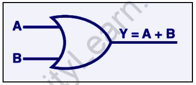
The OR gate’s Boolean expression is Y = A + B, which can be read as Y equals A ‘OR’ B.
A two-input OR basic gate’s truth table is as follows:
| A | B | Y |
| 0 | 0 | 0 |
| 0 | 1 | 1 |
| 1 | 0 | 1 |
| 1 | 1 | 1 |
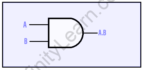
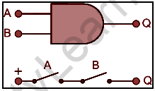
AND GATE:
The output of an AND gate achieves state 1 if and only if all of the inputs are in state 1.
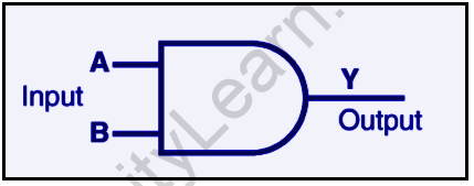
AND gate’s Boolean expression is Y = A.B.
A two-input AND basic gate’s truth table is as follows:
| A | B | Y |
| 0 | 0 | 0 |
| 0 | 1 | 0 |
| 1 | 0 | 0 |
| 1 | 1 | 1 |
NOT GATE:
The output of a NOT gate achieves state 1 if and only if the input does not achieve state 1.
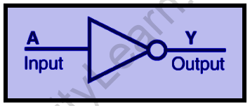
The Boolean expression is Y=A, which translates to Y equals NOT A.
The NOT gate truth table is as follows:
| A | Y |
| 0 | 1 |
| 1 | 0 |
When the three gates (OR, AND, and NOT) are connected in various ways, we get basic logic gates like NAND and NOR, which are the universal building blocks of digital circuits.
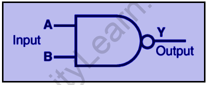
NAND Gate:
This fundamental logic gate is a combination of the AND and NOT gates.
The NAND gate’s Boolean expression is,
Y=A-B
The truth table of a NAND gate is as follows:
| A | B | Y |
| 0 | 0 | 1 |
| 0 | 1 | 1 |
| 1 | 0 | 1 |
| 1 | 1 | 0 |
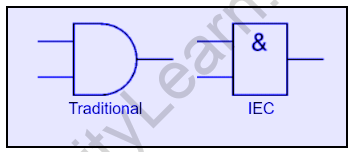
Logic gate symbols
For logic gates, there are two series of symbols. Traditional symbols have distinct shapes that make them easy to identify and are widely used in industry and education. The IEC (International Electrotechnical Commission) symbols are rectangles with a gate function symbol inside. Despite their official status, they are rarely used, but you may need to know them for an exam.
Except for the NOT gate, which has only one input, gates have two or more inputs. Every gate has only one output. Inputs are typically labeled with the letters A, B, C, and so on, while outputs are labeled with the letter Q. On this page, the inputs are displayed on the left and the output is displayed on the right. Some gate symbols have a circle on their output, indicating that their function includes output inversion. It is the same as passing the output through a NOT gate. For example, the NAND (Not AND) gate symbol on the right is the same as an AND gate symbol but with an inverting circle on the output.
Also read: Longitudinal and Transverse Wave


FAQs
What exactly are logic gates?
Logic gates are digital circuits that perform logical operations on the input and generate appropriate output.
What exactly are Universal gates?
Universal gates are created by combining two or more fundamental gates to accomplish a specific logical process. NAND and NOR gates are examples of universal gates.
What is the Boolean formula for OR gate?
If A and B are used as inputs, the OR gate output can be written as Y=A+B.
