Table of Contents
Block Diagram of Computer: The Block Diagram of a Computer system offers a comprehensive view of its primary components and how they interact. Our article delves into the intricacies of this diagram, providing a detailed understanding of a computer’s structure and functionality.
Nowadays, computers play a vital role in our lives, from simple calculations to complex space missions. As technology continues to advance, computers have become an integral part of our daily routines. While we use computers for various tasks, have you ever stopped to think about how they actually work? Like any other machine, computers have a specific architecture with different components that handle input, processing, and producing output.
In this article, we explore the basic block diagram of a computer. Take a look to understand how each part contributes to the overall functioning of a computer system.

What is Block Diagram of Computer System?
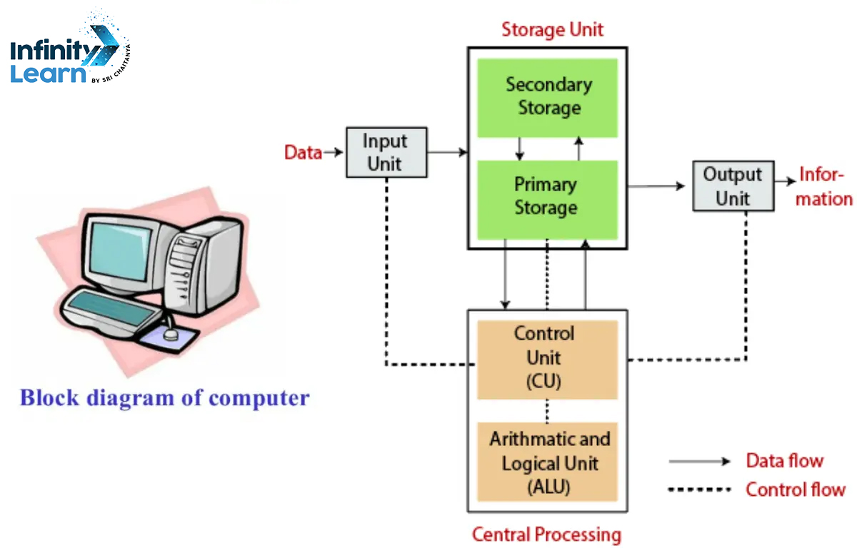
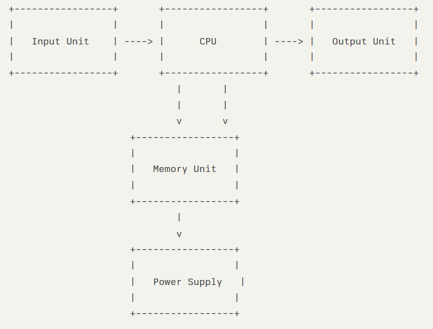
The Block Diagram of a Computer shows how data and instructions flow between the CPU, memory, and I/O devices, managed by the Control Unit. Simply put, it explains how computers work, from taking input, processing it, to giving the desired output. A computer system has three main parts: Input Units, CPU, and Output Units. These parts work together smoothly to perform tasks effectively.
Also Refer: Computer Science Syllabus Class 10
Draw the Block Diagram of Computer

Also Check: 100+ Computer Shortcut Keys from A to Z
Components of a Computer’s Block Diagram
- Input Unit
- Output Unit
- Central Processing Unit (CPU)
- Control Unit (CU)
- Arithmetic and Logic Unit (ALU)
- Memory Unit a) Primary Memory b)Secondary Memory
In a computer’s block diagram, several essential components facilitate its functioning. Here’s a breakdown:
Input Devices:
- Acts as the initial point for data entry into the computer system.
- Comprises devices like keyboards, mice, and scanners.
- Converts raw data into machine-readable form.
- Transmits converted data to the computer’s main memory.
- Facilitates the seamless exchange of information between users and computers.
Central Processing Unit (CPU):
- Often referred to as the brain of the computer, the CPU executes instructions, performs calculations, and manages data manipulation.
- Functions as the computer’s “brain,” overseeing all tasks and operations.
- Executes arithmetic and logical operations.
- Controls data processing, software operations, and hardware interactions.
- Consists of the Arithmetic Logic Unit (ALU) and Control Unit (CU).
- ALU handles arithmetic and logical operations, while the CU manages instructions and coordination.
Memory:
- Serves as the central storage hub for data within the computer system.
- Divided into primary (e.g., RAM) and secondary memory (e.g., hard disks).
- Primary memory stores temporary data for quick access.
- Secondary memory provides long-term storage capabilities.
- Works closely with the CPU to facilitate swift data access and processing.
Output Devices:
- Delivers processed information to users in readable formats.
- Includes devices like printers and monitors.
- Presents data as either soft copy (on-screen) or hard copy (on paper).
- Converts binary data into human-readable formats.
- Completes the cycle of information exchange by enabling users to interpret and utilize results effectively.
Control Unit: The Control Unit coordinates and manages the flow of data and instructions within the computer. It fetches instructions from memory, decodes them, and directs the CPU and other components to execute the required operations.
Bus System: The bus system consists of a set of communication pathways that enable data transfer between different components of the computer. It facilitates the exchange of information between the CPU, memory, input/output devices, and other peripherals.
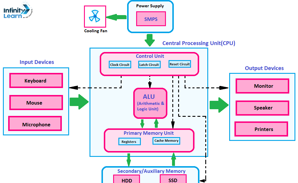
Block Diagram of Computer Hardware Devices
A block diagram of computer hardware devices provides a visual representation of the main components of a computer system and their interactions.

- Input Unit:
- Devices such as keyboards, mice, and scanners that allow users to input data into the computer.
- Central Processing Unit (CPU):
- The main processing component, which includes:
- Control Unit (CU): Manages and controls the operations of the computer.
- Arithmetic Logic Unit (ALU): Performs all arithmetic and logical operations.
- The main processing component, which includes:
- Memory Unit:
- Composed of:
- Primary Memory (RAM): Temporary storage for data and programs currently in use.
- Secondary Memory (HDD/SSD): Long-term storage for data and applications.
- Composed of:
- Output Unit:
- Devices like monitors and printers that present the processed data to the user.
- Power Supply:
- Converts electrical power from an outlet into usable power for the computer components.
This block diagram provides a clear and concise overview of the essential block diagram of computer hardware devices, illustrating how they interact with each other.
Block Diagram of Computer Network
A block diagram of a computer network illustrates the major components and their interconnections in a network. It provides a high-level overview of how devices communicate with each other. Key elements typically shown in a network block diagram include:
- Network nodes: Devices like computers, servers, routers, switches, printers, etc. that are connected to the network
- Network links: Physical or wireless connections between nodes
- Network devices: Components that facilitate network communication like routers, switches, firewalls, etc.
- Network topology: The layout and arrangement of network nodes and links
Symbols Used in Block Diagram of Computer Network
Network block diagrams use standardized symbols to represent different network components:
- Rectangles or squares for network nodes like computers and servers
- Circles or rounded rectangles for network devices like routers and switches
- Lines to show network links, with line styles indicating connection type (e.g. solid for wired, dashed for wireless)
- Clouds to represent external networks or the internet
FAQs on Block Diagram of Computer System
What is a Block Diagram?
A block diagram serves as a visual depiction of a system or process, illustrating the connections between its various components or stages. It employs blocks connected by lines or arrows to signify the flow of information or signals.
What is a function block diagram in computer?
In computer science, a function block diagram is a visual representation of a computer program or algorithm using blocks to represent functions or operations, and lines to indicate the flow of data between them.
What is a block diagram with an example?
A block diagram is a graphical representation of a system or process using simple blocks to represent components or stages, connected by lines or arrows to show the flow of information or signals between them. Each block typically represents a specific function or operation within the system.
What is a block diagram of a computer class 9?
A block diagram of a computer in Class 9 typically showcases the basic components and their interconnections within a computer system. A computer block diagram illustrates the fundamental components of a computer system and their interactions.
What is a computer block diagram and its parts?
A computer block diagram is a visual representation of the main components of a computer system and their connections. It typically includes the Central Processing Unit (CPU), Memory (RAM and ROM), Input/Output (I/O) Devices, Storage Devices, Motherboard, Bus System, Power Supply Unit (PSU), and Cooling System. These parts work together to process data and execute tasks within the computer.


