Measurement of Length
Introduction
Length is a fundamental physical quantity. The devices generally used in the laboratory for measuring the length of a body are metre scale, vernier callipers, screw gauge and spherometer. The value of the marked division on metre scale is 1 mm. It can be used for measuring length with an accuracy of 1 mm. So the least count of a metre scale is 1 mm.
When we have to measure length accurately up to l/10th or l/100th of a millimetre, the following instruments are used :
(а) Vernier Callipers
(b) Screw Gauge
(c) Spherometer
Metre
It is the distance between the two parallel lines marked on a platinum-iridium rod preserved at a constant temperature of 273.16 K and pressure 1 bar in the International Bureau of Weights and Measures at Severes, near Paris in France.
Since 1960, the standard metre is defined as the distance which contains 16, 50, 763.73 wavelengths of orange-red light of krypton-86 (8636Kr) source kept at the temperature of triple point of nitrogen (which is 63.18 K at pressure 0.125 x 10⁵ N m-2).
Metre Scale
It is a wooden or steel scale and is the simplest instrument used in laboratory for measuring small lengths. The smallest division made on this metre scale is 1 mm, hence the length measured is accurate only up to 1 mm.
The following important precautions must be observed by the students to avoid certain errors which are caused due to use of the scale in wrong manner :
- The edge of the scale should be kept along the length of the object. Inclined scale gives more length.
- One edge of the object (whose length is being measured) should coincide with a fixed mark on the scale.
- Use of zero mark on scale should be avoided because that edge of the scale is generally worn out.
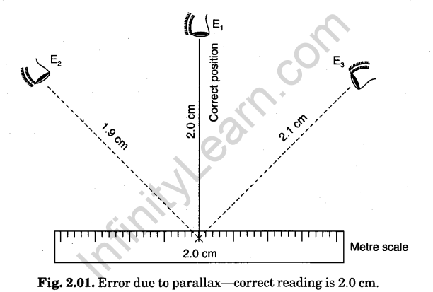
- The reading should be taken keeping one eye closed and the other eye directly over the mark. Reading with an inclined eye will be wrong due to error of parallax (see Fig. 2.01).
- Without disturbing the object and the metre scale, eye is moved to other edge of the object and its reading is taken on scale. Difference of the readings of the two edges on scale gives the length of the object.
Vernier Scale
Construction. It is a device invented by a French Mathematician, Pierre Vernier and is called Vernier after the name of the inventor scientist.
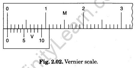
It consists of a main scale M along which an auxiliary scale slides, known as vernier scale V, as shown in Fig. 2.02.
Principle (Theory). In the common form, the divisions on the vernier scale V are smaller in size than the smallest division on the main scale M but in some special cases the size -of the vernier division may be larger than the main scale division.

The difference between the values of one main scale division and one vernier scale division is known as Vernier Constant (V.C.). This is the smallest distance that can be accurately measured with the vernier scale and so it is also called the Least Count (L.C.) of the vernier scale.
Reading a Vernier Scale
Let one main scale division be 1 mm and 10 vernier scale divisions coincide with 9 main scale divisions (Fig. 2.02).
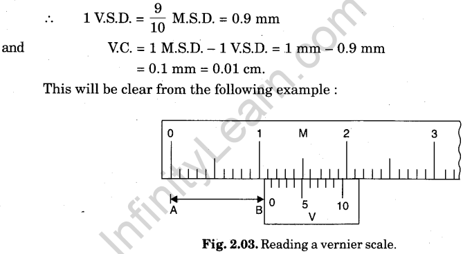
If we have to measure a length AB, the end A is coincided with the zero of main scale and the end B coincided with the zero of the vernier scale (Fig. 2.03). Its enlarged view is given in Fig. 2.04.
Length AB > 1.0 cm < 1.1 cm.
Let 6th division of vernier scale coincide with 1.6 cm of main scale division. From diagram, it is clear that the distance between 5th division of vernier scale and 1.5 cm of main scale is equal to one V.C. and distance between zero mark of vernier scale and 1.0 cm mark on the main scale is equal to 6 times the vernier constant.
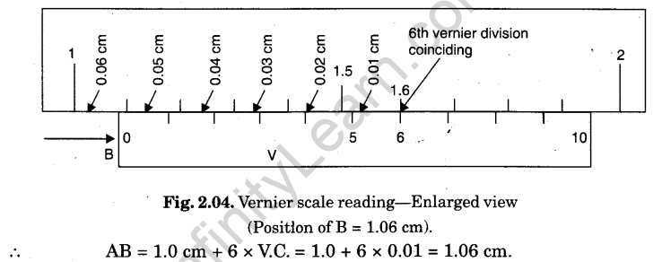
The reading with vernier scale is read as given below :
(i) Take the main scale reading (AO before on the left of the zero of the vernier scale.
(ii) Find the number (n) of vernier division which just coincides with any of the main scale division. Multiply this number (n) with vernier constant (V.C.)
(iii) Total reading = (N + n x V.C.)
Caution. The main scale reading with which the vernier scale division coincides has no connection with the reading.
The vernier scales commonly used are as follows :


Vernier Callipers
Construction. Its main parts are :
1. Main scale. It consists of a steel metallic strip M, graduated in cm and mm at one edge and in inches and tenth of an inch at the other edge on same side. It carries fixed jaws A and C projected at right angle to the scale as shown in Fig. 2.05.
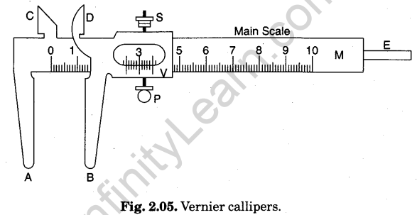
2. Vernier scale. A vernier scale V slides on the strip M. It can be fixed in any position by screw S. It is graduated on both sides. The side of the vernier scale which slides over the mm side has ten divisions over a length of 9 mm, i.e., over 9 main scale divisions and the side of the vernier scale which slides over the inches side has 10 divisions over a length of 0.9 inch, i.e., over 9 main scale divisions.
3. Movable jaws. The vernier scale carries jaws B and D projecting at right angle to the main scale. These are called movable jaws. When vernier scale is pushed towards A and C, then as B touches A, straight side of D will touch straight side of C. In this position, in case of an instrument free from error, zeros of vernier scale will coincide with zeros of main scales, on both the cm and inch scales.
(The object whose length or external diameter is to be measured is held between the jaws A and B, while the straight edges of C and D are used for measuring the internal diameter of a hollow object.)
4. Metallic strip. There is a thin metallic strip E attached to the back side of M and connected with vernier scale. When jaws A and B touch each other, the edge of strip E touches the edge of M. When the jaws A and B are separated, E moves outwards. This strip E is used for measuring the depth of a vessel.
Zero Error and Zero Correction
Definition. If the zero of the vernier scale does’ not coincide with the zero of main scale when the jaw B touches A and the straight edge of D touches the straight edge of C, then the instrument has an error called zero error. Zero error is always algebraically subtracted from observed length.
Zero correction has a magnitude equal to zero error but its sign is opposite to that of the zero error. Zero correction is always algebraically added to observed length.
Positive and Negative Zero Error
Zero error may be positive or negative, depending upon whether the zero of vernier scale lies to the right or to the left of the zero of the main scale. In such case, a correction has to be applied to the observed reading.
(a) Zero error is positive when the zero of vernier scale lies to the right of the zero of the main scale, when jaws A and B are in contact. To find the zero error read the main scale reading (AO on the left of zero of vernier scale and also the vernier division (n) coinciding with any main scale division, then
Zero error = + (N + n x V.C.).
To get the correct reading, this quantity has to be subtracted from the observed reading.
(b) Zero error is negative when the zero of vernier scale lies to the left of the zero of the main scale when jaws A and B are in contact. To find the zero error in this case, proceed as described below :
Imagine the main scale extended to negative side, i.e., to the left of zero. If zero of vernier scale is to the right of first negative division of main scale, then main scale reading N = -1 mm = – 0.1 cm. If x th V.S.D. coincides with any M.S.D., then zero error = (N + n x V.C.) which comes out to be negative.
Suppose, x = 7, then zero error = (- 0.1 cm + 7 x 0.01 cm)
= (- 0.10 + 0.07) = – 0.03 cm.
Zero correction = + 0.03 cm.
Exercise
Using a vernier callipers to find its vernier constant, zero error and zero correction.
Procedure
1. Determination of least count. Note the value of the main scale division and count the number n of vernier scale divisions. Slide the movable jaw till the zero of vernier scale coincides with any of the mark on the main scale and find the number of divisions (n – 1) on the main scale coinciding with n divisions on vernier scale. Then

2. Determination of zero error and zero correction. For this purpose, movable jaw B is brought in contact with fixed jaw A.
One of the following three situations will arise :
(i) Zero of vernier scale coincides with zero of main scale (Fig. 2.06).
In this case, zero error and zero correction, both are nil. Actual length = observed (measured) length.
(ii) Zero of vernier scale lies on the right of zero of main scale (Fig. 2.07).
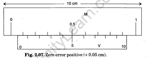
Here, 5th vernier scale division is coinciding with any main scale division.
Hence, N – 0, n = 5, L.C. = 0.01 cm.
Zero error = N + n x (L.C.) = 0 + 5x 0.01 = + 0.05 cm.
Zero correction = – 0.05 cm.
Actual length will be 0.05 cm less than the observed (measured) length.
(iii) Zero of vernier scale lies on the left of zero of main scale (Fig. 2.08).

Here, 6th vernier scale division is coinciding with any main scale division.
In this case, zero of vernier scale lies on the right of – 0,1 cm reading on main scale.
Hence, N – – 0.1 cm, n = 6, L.C. = 0.01 cm.
(Zero error = N + n x (L.C.) = — 0.1 + 6 x 0.01 = – 0.04 cm.
Zero correction = + 0.04 cm.
Actual length will be 0.04 cm more than the observed (measured) length.
Principle of a Micro Meter Screw
With vernier callipers ordinarily available in the laboratory, we measure length correct up to 0.01 cm. When lengths are to be measured with greater accuracy, say up to 0.001 cm, screw gauge and spherometer are used which are based on the principle of micrometre screw.
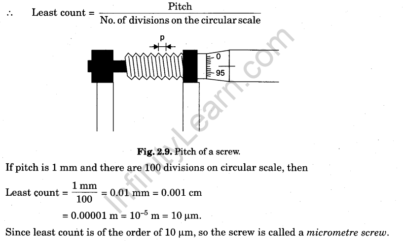
If an accurately cut single threaded screw is rotated in a closely fitted nut, having evenly spaced threads, matching the threading on the screw, then in addition to the circular motion of the screw there is a linear motion of the screw head in the forward or backward direction, along the axis of the screw. The linear distance moved by the screw, when it is given one complete rotation is equal to the distance between two consecutive threads, as measured along the axis of the screw. This distance is called the pitch of the screw and is represented hyp (Fig. 2.9). In most of the cases it is either 1 mm or 0.5 mm. A circular cap or disc is fixed on one end of the screw and the circumference of the cap or disc is normally divided into 100 or 50 equal parts. If it is divided into 100 equal parts, then the screw moves forward or backward by 1/100 of the pitch, if the circular scale is rotated through one circular scale division. It is the minimum distance which can be accurately measured and so is called the least count of the screw.
Screw gauge and the spherometer which work on the principle of micrometre screw, consist essentially of the following two scales :
(i) Linear or Pitch scale. It is a scale running parallel to the axis of the screw. It is graduated into millimetre or half millimetre.
(ii) Circular or Head scale. It is marked on the circumference of the circular disc or the cap attached to the screw.
Screw Gauge
Screw gauge (Fig. 2.10) works on the principle of micrometer screw. It consists of a U- shaped metal frame M. At one end of frame M, a small solid piece A made of gun metal is fixed. It is called stud and it has a plane face. The other end N of M carries a cylindrical hub H. The hub extends few millimetre beyond the end of the frame. On the cylindrical hub along its axis, is drawn a line known as reference line. On the reference line graduations are in millimetre and half millimetre depending upon the pitch of the screw. This scale is called linear scale or pitch scale. A nut is threaded through the hub and the frame N. Through the nut moves a screw S made of gun metal. The front face B of the screw, facing the plane face A, is also plane. A hollow cylindrical cap K, is capable of rotating over the hub when screw is rotated. It is attached to the right hand end of the screw. As the cap is rotated the screw either moves in or out. The levelled circular surface E of the cap K is divided into 50 or 100 equal parts. It is called the circular scale or head scale. Right hand end R of K is milled for proper grip and called ritchet.
In most of the instruments the milled head R is not fixed to the screw head but turns it by a spring and ratchet arrangement such that when the body is just held between faces A and B, the spring yields and milled head R turns without moving in the screw.

In an accurately adjusted instrument when the faces A and B are just touching each other, the zero marks of circular scale and pitch scale exactly coincide.
Zero Error and Zero Correction
In some instruments either due to wear and tear or due to manufacturing defect, the zero mark of circular scale does not coincide with the zero of the pitch scale when the faces A and B are just touching each other. Such instruments possess zero error and zero correction. If the zero of the circular scale advances beyond the reference line, the zero error is negative and zero correction is positive. If it is left behind the reference line the zero error is positive and zero correction is negative.
Example. If zero of circular scale advances beyond the reference line by 3 divisions, zero correction = (+ 3 x least count) and if the zero of circular scale is left behind the reference line by 3 divisions, zero correction = (- 3 x least count).
Back-Lash Error
On account of wear and tear or loose fitting, there is some space left for the play between the screw and the nut. In such instruments if the screw is advanced by turning it in one direction and then it is rotated back, the screw may not move along the axis for an appreciable rotation of the head. The error due to it is called back-lash error of the screw. To reduce this error, the screw must always be rotated in the same direction, for a particular set of observations.
Determination of Pitch, Least Count and Zero Error of Screw Gauge
1. Determination of pitch and least count. Pitch is the linear distance travelled by screw in one complete rotation and is equal to the distance between two consecutive threads. Note the value of the linear (pitch) scale division. Rotate screw to bring zero mark on circular (head) scale on reference line. Note the number of divisions on linear scale uncovered by the cap.
Now, give the screw a few known number of rotations. (One rotation is completed when zero of circular scale again arrives on the reference line). Again note the linear scale reading. Find difference of two readings on linear scale to find distance moved by the screw.

2. Determination of zero error and zero correction. For this purpose, the screw is rotated forward till plane face B of the screw just touches the fixed plane face A of the stud and edge of cap comes on zero mark of linear scale. Screw gauge is held keeping the linear scale vertical with its zero downwards.
One of the following three situations will arise :
(i) Zero mark of circular scale comes on the reference line.
In this case, zero error and zero correction, both are nil (Fig. 2.11).
Actual thickness = Observed (measured) thickness.

(ii) Zero mark of circular scale remains on right of reference line and does not cross it (Fig. 2.12). Here 2nd division on circular scale comes on reference line. Zero reading is already 0.02 mm. It makes zero error + 0.02 mm and zero correction – 0.02 mm.
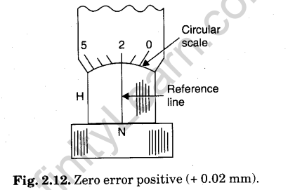
Actual thickness will be 0.02 mm less than the observed (measured) thickness.
(iii) Zero mark of circular scale goes to left of reference line after crossing it (Fig. 2.13). Here zero of circular scale has advanced from reference line by 3 divisions on circular scale. A backward rotation by 0.03 mm will make reading zero. It makes zero error -0.03 mm and zero correction + 0.03 mm.

Actual thickness will be 0.03 mm more than the ‘observed (measured) thickness.
Spherometer
Principle. It works on the principle of micrometre screw (Section 2.09) It is used to measure either very small thickness or the radius of curvature of a spherical surface that is why it is called a spherometer.
Construction. It consists of a metallic tripod framework supported on three fixed legs of equal lengths (Fig. 2.14). The tips of the three legs lie on the corners of an equilateral triangle and they always lie in same plane. At the centre of the tripod frame is fixed a vertical nut. An accurately cut screw passes through this nut. The axis of the screw is parallel to the three legs. A large circular disc D terminating into a milled head is attached at the top of the screw.
The circumference of circular disc is divided into 100 or 200 equal parts. A small vertical scale, P, usually divided into millimetre or half millimetre is fixed at one end of the tripod frame. The scale P is parallel to the axis of screw and it just touches the rim of the circular disc. P is also known as Pitch scale.

Determination of Least Count. To measure the pitch of the screw, first find the value of 1 division on pitch scale. Then bring zero of circular scale opposite to pitch scale and rotate the screw by n complete rotations (4 or 5). Note the distance d moved by the screw on the pitch scale. The
pitch p of the screw is given by,p= d/n mm = 1 mm.
If there are N divisions in the circular scale on the circumference of the disc,
least count of the screw = P/N mm = 0.001 cm.
Measurements
(i) To measure the thickness of a glass strip, place the spherometer on a big size glass slab so that its three legs rest on it. Raise the screw sufficiently so that a small glass strip, whose thickness is to be determined, could be placed below the screw. Then gently turn the screw downwards till the screw tip just touches the surface of the glass strip.
To test this, press at one of the outer legs of the spherometer gently and try to introduce a thin paper below either of the other two legs or the central screw. In case it cannot be introduced at any of the place, then the screw just touches the upper surface of the glass strip. Note the reading of the circular scale which is in line with the pitch scale. Remove the glass strip from below the screw and turn the screw downwards till the tip of the screw just touches the plane surface of the glass slab. In doing so, count the number of complete rotations n1 made by the disc taking initital reading of circular scale as reference point and note the number of additional circular scale divisions x which are in excess of the complete rotations.
Then, thickness of the strip t = (n1 x pitch + x x L.C.)
The value of x can also be calculated by the following method:
If a be the initial and b be the final reading of the circular scale then :
(1) For circular scales having clockwise graduation, x = (a – b) and for a circular scale having anticlockwise graduation, x = (b – a), if zero of circular scale does not move across the vertical scale P.
(2) For clockwise graduation, x = [(100 -a)-b] and for anticlockwise graduation, x= [(100 — b) — a]
if zero of circular scale moves across the vertical scale P.
(ii) To measure the radius of curvature R of the convex surface, the spherometer is placed on the convex surface so that all the three legs and the screw are touching it. In this position find the circular scale division opposite the pitch scale.
Next place the spherometer on the plane surface of glass slab and move the screw downward till the central screw touches the glass surface. In doing so count the number of complete rotations n1 made by the disc by taking the initial reading of the circular scale as reference point and note the number of additional circular scale divisions x which are in excess of the complete rotations.
Then, distance moved by central screw, h = (n1 x pitch + x x L.C.)
[Note. To find the radius of curvature of concave surface first put the spherometer on plane surface, then put it on concave surface to find h].
Let AX2EX1B (Fig. 2.15) represent the vertical section of the sphere of which the given surface forms a part, the vertical section passes through one of the outer legs A and central
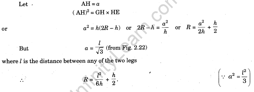
screw G and the centre of the sphere O. The third leg C is not visible. Let GH = h, the height of central screw above the plane ABC, which is measured by the spherometer. (h is called Sagitta.)
