Table of Contents
Measurement of Electromotive Force and Potential Difference


Electric (Electrostatic) potential and Electric potential difference
Definition. Electric potential at a point in the electric field of a charge (field charge) is defined, (or measured) as the work done in moving a unit positive charge (test charge) from infinity (i.e., from outside the field) to that point (provided that the bringing of the test charge does not effect the original field configuration.)
It is represented by the symbol V. Its S.I. unit is volt. It is scalar (being work). Electric potential difference between two points in the electric field of a field charge is defined as the work done in moving a test charge from one point to the other.
Electromotive Force and potential difference of a cell
- Electromotive Force: The chemical force which makes the positive ions inside a cell to move from negative to positive terminal inside the cell, is called electromotive force (e.m.f.) of the cell. It is represented by the symbol E (or ε). Its unit is volt. It is a scalar quantity because it is the potential difference.
It is equal to the potential difference between the two terminals of the cell, when the cell is in open circuit i.e., giving no current.
E.M.F. is independent of
(i) Plates (electrodes) area
(ii)Plates separation
(iii) Electrolyte quantity. - Potential Difference: It is the potential difference between the two terminals of the cell, when it is in close circuit i.e., giving current. It is represented by the symbol V. Its unit is volt.


Internal resistance of cell
The resistance offered by the electrolyte of the cell to flow of ions through it, is called internal resistance of the cell. It is represented by the symbol r. Its unit is ohm (Ω).
Internal resistance depends upon
- Plates (electrodes) area inside the electrolyte.
- Plates separation
- Electrolyte nature and concentration.
- Temperature
- Use of cell. (Passage of time)
Relation between E.M.F., P.D. and internal resistance of a cell
Circuit in shows a cell of e.m.f. E and internal resistance r, connected to an external resistance R. The circuit has total resistance (R + r) and current I in circuit is given by
Potentiometer
(a) Potentiometer: is a device used to measure the internal resistance of cell, to com¬pare the e.m.f. of two cells and potential difference across a resistor.
(b) Principle:
It works on the principle that when a constant current flows through a wire of uniform thickness and material, potential difference between its two points is directly proportional to the length of the wire between the two points. It is a device used to measure the internal resistance of a cell, to compare the e.m.f. of two primary cells etc.
V = IR …(1)
(c) Construction:
A potentiometer consists a long wire of uniform cross-sectional area, usually 4 to 10 m long, of material having high resistivity and low temperature coefficient such as constantan or manganin. These wires are stretched parallel to each other on a broad wooden board by the side at a metre scale. The wires are joined in series by thick copper strips. A battery of constant e.m.f. (battery eliminator) is connected to the ends P and Q of wire, called driving or auxiliary cell. A jockey J, with a sensitive galvanometer G, is made to slide on the wire PQ.
Note. The number of wires can be increased to increase l and decrease k = V/l.
A lower value of k makes potentiometer more sensitive and accurate.
(d) Working:
A fully charged auxiliary battery B (Battery eliminator) having a constant and high e.m.f. is connected between terminals P and Q through an ammeter A and a rheostat (as shown in circuit diagram, experiment 5 : Section A). This provides an adjustable potential gradient along the potentiometer wire. Positive terminal of the battery is connected to terminal P. Positive terminals of other cell or cells are also connected to same terminal P.
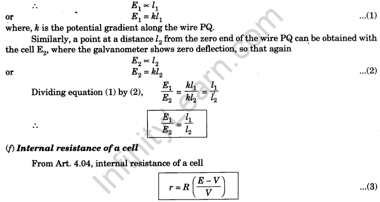
(e) Comparison of e.m.f.’s of two cells:
With the help of a voltmeter we can measure only the terminal potential difference of a cell, but using a potentiometer we can determine the value of e.m.f. (electromotive force) of a given cell. For this purpose, we complete the circuit diagram as shown in The e.m.f. (E) of the auxiliary battery B is constant and more than that of given cell. Insert the key K. A constant current I flows through the potentiometer wire PQ and a potential gradient k = Iσ is set up, where a is the resistance per unit length of the potentiometer wire.
The positive terminals of the cells E1 and E2 are connected to the zero end terminal P of the potentiometer, whereas the negative terminals are connected through a two-way key to a galvanometer, a resistance box and a jockey. When the cell Ex is in circuit, on sliding the jockey gently along the potentiometer wire PQ a point J, say at a distance l1 from the zero end, is obtained where the galvanometer shows zero deflection. In such a case the – ve terminal of the cell E1 and the point J on the potentiometer wire are at the same potential. The zero end of the potentiometer wire and the + ve terminal of cell E1 are also at the same potential. Hence, fall of potential along the length l1 of the potentiometer wire is equal to the e.m.f. of the cell E1 as no current is being drawn from the cell. As the fall of potential along a wire of a uniform area of cross section is proportional to its length.
For determination of internal resistance of a cell by a potentiometer, the circuit arrange¬ment used is shown in E is the cell whose internal resistance is to be measured. By adjusting the rheostat and closing key K1 if l1 is the length of the potentiometer wire to the point where a balance point is obtained in an open circuit i.e., K2 is open, then
(g) Important Precautions to be taken in Potentiometer Experiments
- The auxiliary battery B used for producing potential gradient along the potentiometer wire should be fully charged to have a constant e.m.f. Its e.m.f. should be greater than the e.m.f. of each cell which is to be compared.
- Positive terminals of all the cells must be connected to the terminal P where that of auxiliary battery is connected.
- Terminal P should be taken as zero of the scale for measuring the balancing length.
- A sensitive galvanometer should be used to find the null point. It should be protected with a resistance box (R.B.), put in series while finding approximate position of null point. Resistance in box should be made zero when exact position of the null point is to be located.
- The approximate position of null point must be brought in the middle of the last wire, by putting jockey J there and adjusting wire current by the rheostat.
- Current should be passed through the wire only when taking observations, to avoid unnecessary heating of wire, which causes change of resistance changing the potential gradient, (k = Iσ).
- In case, null point is not obtained on the potentiometer wire i.e., one-side deflection is obtained when jockey is kept at the two ends of the wires used, following checks must be made.
(i) Connections must be correct, neat, tight and continuous (no connecting wire is broken). For correct connections, positive terminal of battery and cells be connected at one point,
(ii) Measure the e.m.f. of the auxiliary battery. The e.m.f. must be full and stable to ensure that the battery is fully charged. The of battery must be more than the e.m.f. of either cell used.
(iii) Make rheostat resistance in circuit zero so that maximum current passes through the potentiometer wires.
If the above checks do not help, change the potentiometer. (It has some defect which you can not remove).