Table of Contents
Resistance is a fundamental concept in physics that quantifies the opposition encountered by an electric current flowing through a conductor. It is denoted by the symbol “R” and is measured in ohms (Ω). The resistance of a conductor depends on its material, length, cross-sectional area, and temperature.
Resistance Definition


Resistance is a measure of the opposition to the flow of electric current in a circuit. It is a property of a material or component that determines the amount of current that will flow through it for a given voltage.
Resistance Formula
Ohm’s Law states that the current passing through a conductor is directly proportional to the voltage applied across it and inversely proportional to its resistance. Mathematically, Ohm’s Law can be expressed as:
V = I x R
Where:
V represents the voltage across the conductor in volts (V).
I represent the current flowing through the conductor in amperes (A).
R represents the resistance of the conductor in ohms (Ω).
Rearranging the resistance formula, we can solve for resistance:
R = V / I
The resistance formula shows that resistance is equal to the ratio of voltage to current. It indicates the amount of potential difference required to produce a certain current through a conductor. The higher the resistance, the greater the voltage needed to maintain a specific current.


Unit of Resistance
The SI unit of resistance is the ohm (Ω). It is a derived unit that represents the ratio of voltage to current in an electrical circuit. One ohm is equal to one volt per ampere (V/A), which means that a circuit has a resistance of one ohm if a voltage of one volt is applied across it and it allows a current of one ampere to flow.
Factors Affecting Resistance
Resistance depends on various factors. The resistivity of the material is a crucial property that determines the resistance. Materials with high resistivity, such as rubber or glass, have high resistance, while materials with low resistivity, such as copper or silver, have low resistance.
The length and cross-sectional area of the conductor also affect resistance. Longer conductors have higher resistance, while wider or thicker conductors have lower resistance. This relationship is described by the resistance formula:
R = (ρ x L) / A
Where:
ρ (rho) represents the resistivity of the material in ohm-meters (Ω·m).
L represents the length of the conductor in meters (m).
A represents the cross-sectional area of the conductor in square meters (m²).
Temperature also plays a role in resistance. Most materials increase their resistance as temperature rises, although this effect varies among materials.
Resistors in Series
Consider a simple circuit with three resistors R1, R2 and R3 connected in series along with an Ammeter and a plug key.
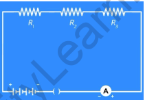
Resistors in series
Close the plug key and note down the Ammeter reading. Next, place the ammeter between the resistors R1 and R2, and then between R2 and R3 and note down the respective ammeter readings.
From the readings recorded, we see that the current is the same in each reading. Let this current be ‘I’ ampere. So, in a series of combination of resistors, the current flowing is the same throughout the circuit.
Now remove the ammeter and insert a voltmeter across the start of the first resistor and the end of the third resistor. Then plug the key and note the potential difference across the resistors. Let’s say it’s ‘V’ volts.
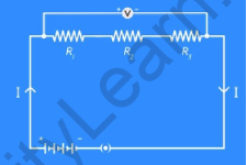
Disconnect the voltmeter and insert three voltmeters in the circuit, one across each of the resistors. Then plug the key and measure the potential difference across each of the resistors. You will notice that the potential difference across each of the resistors is different. Let’s call them V1, V2, and V3 respectively.
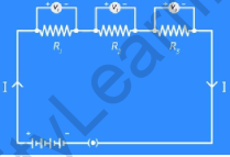
Even though the voltages are different, you will notice that the potential difference V is equal to the sum of the potential differences V1, V2, and V3.
V = V1 + V2 + V3 … (1)
Let the 3 resistors together form resistance of R ohms. Thus by Ohm’s Law,
V = IR … (2)
Similarly, applying Ohm’s law for each resistor,
V1 = IR1 … (3)
V2 = IR2 … (4)
V3 = IR3 … (5)
Now on substituting equations (2), (3), (4), and (5) in equation (1), IR = IR1 + IR2 + IR3
∴ Rs = R1 + R2 + R3
Thus, when two or more resistors are connected in series, then the overall combined resistance, denoted by ‘Rs’, is the sum of the individual resistances.


Resistors in Parallel
Consider a simple circuit with three resistors R1, R2 and R3, an Ammeter and a plug key. In this circuit, we have 3 resistors of different values connected in parallel since all the resistors have common start and endpoints. Let the points be X and Y.
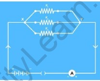
Resistors in parallel
The potential difference is always measured between two points. If the two points are common, it means the potential difference across each of the resistors will be the same.
The points X and Y are common for each of the resistors and also for the battery. So, if the potential difference across the battery is ‘V’ volts, then the potential difference across each resistor will also be V volts.
In this circuit, the current across each resistor will not be the same.
Let the current across R1, R2, and R3 be I1, I2, and I3 respectively. Let the total current flowing in the circuit be I. Then the total current I will be equal to the sum of the separate currents flowing through each of the resistors.
By Ohm’s Law,
I = V/Rp … (2)
Where Rp is the combined resistance of the resistors in parallel.
Also,
I1 = V/R1… (3)
I2 = V/R2… (4)
I3 = V/R3… (5)
The potential difference across each resistor will be the same as that of the battery. Substituting equations (2), (3), (4), and (5) in (1),
V/Rp = V/R1 + V/R2 + V/R3
∴ 1/Rp= 1/R1 + 1/R2 + 1/R3
Thus, when resistors are connected in parallel, the reciprocal of the equivalent resistance Rp is equal to the sum of the reciprocals of the individual resistances.
Solved Examples on Resistance Formula
Example 1: A circuit has a voltage of 12 volts applied across a resistor, and a current of 2 amperes flows through it. Calculate the resistance.
Solution:
Given:
Voltage (V) = 12 volts
Current (I) = 2 amperes
Using Ohm’s Law:
R = V / I
R = 12 V / 2 A
R = 6 ohms
Therefore, the resistance of the circuit is 6 ohms.
Example 2: A wire has a length of 10 meters and a cross-sectional area of 2 square millimetres. The resistivity of the material is 1.7 x 10⁻⁸ ohm-meters. Calculate the resistance of the wire.
Solution:
Given:
Length (L) = 10 meters
Cross-sectional area (A) = 2 mm2 = 2 x 10⁻⁶ m2
Resistivity (ρ) = 1.7 x 10⁻⁸ ohm-meters
Using the resistance formula:
R = (ρ x L) / A
R = (1.7 x 10⁻⁸ ohm-meters x 10 meters) / (2 x 10⁻⁶ m2)
R = (1.7 x 10⁻⁷ ohm-meters) / (2 x 10⁻⁶ m2)
R = 0.085 ohms
Therefore, the resistance of the wire is 0.085 ohms.
Example 3: As shown in the figure, two resistors with resistances 10 Ω and 15 Ω are connected to a 5 V battery. Find the:
- Total resistance of the circuit
- Potential difference across the 15 Ohms resistor
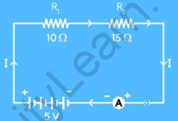
Figure 1
Given:
Resistance (R1) = 10 Ω Resistance (R2) = 15 Ω Potential difference (V) = 5 V
To find:
- Total resistance of the circuit (Rs)
- Potential difference across the 15 Ohms resistor (V2)
Formula:
- Rs = R1 + R2
- V2 = IR2
From the circuit diagram, the two resistors are connected in series. ∴
Total Resistance of the circuit is given by
Rs = R1 + R2
∴ Rs = 10 + 15 = 25Ω ∴ Rs = 25Ω
Therefore, the total resistance of the circuit is 25Ω. Applying Ohm’s law to the entire circuit,
V = IRs
∴ 5 = I ✕ 25
∴ I = 5/25 ∴ I = 0.2A
When resistors are connected in series, the current flowing in the circuit will be the same at every point in the circuit.
Therefore, by using Ohm’s law, V2 = IR2
∴ V2 = 0.2 x 15 = 3V
Therefore, the potential difference across the 15 Ohms resistor is 3V.
FAQ’s on Resistance Formula
What is resistance?
Resistance is the measure of opposition encountered by an electric current as it flows through a conductor. It quantifies the ability of a material to resist the flow of electrons.
What is the SI unit of resistance?
The unit of resistance is the ohm (Ω). It is named after the German physicist Georg Simon Ohm.
What is Ohm’s Law?
Ohm's law states that the current flowing through a conductor is directly proportional to the voltage applied across it and inversely proportional to its resistance. It can be expressed mathematically as I = V/R, where I is the current in amperes, V is the voltage in volts, and R is the resistance in ohms.
What is the symbol for resistance?
The symbol of resistance is Ω.
How can resistance be measured?
Resistance can be measured using an instrument called a multimeter. The multimeter is capable of measuring various electrical quantities, including resistance. To measure resistance, the multimeter is set to the resistance (ohms) mode, and the test probes are connected to the ends of the component or material whose resistance is being measured. The multimeter applies a known small voltage to the component and measures the resulting current flowing through it. Based on Ohm's law (V = IR), the resistance can be calculated by dividing the measured voltage by the measured current.
How is resistance related to current and voltage?
Resistance is related to current and voltage through Ohm's Law, which states that the current flowing through a conductor is directly proportional to the voltage across it and inversely proportional to its resistance. Mathematically, it can be expressed as V = I * R, where V is voltage, I is current, and R is resistance.
What factors affect the resistance of a conductor?
The resistance of a conductor depends on several factors, including the material of the conductor, its length, its cross-sectional area, and the temperature at which it operates.
How does the length of a conductor affect resistance?
The resistance of a conductor is directly proportional to its length. Longer conductors have higher resistance, assuming all other factors remain constant.
How does the cross-sectional area of a conductor affect resistance?
The resistance of a conductor is inversely proportional to its cross-sectional area. Wider or thicker conductors have lower resistance, assuming all other factors remain constant.
What is resistivity?
Resistivity is the inherent property of a material that determines its resistance to the flow of electric current. It is denoted by the symbol ρ (rho) and is measured in ohm-meters (Ω·m).
How does temperature affect resistance?
For most materials, including metals, resistance increases with an increase in temperature. This relationship is known as positive temperature coefficient. However, there are a few exceptions, such as certain semiconductor materials, which exhibit negative temperature coefficients.