Table of Contents
Current Electricity – Sources and Accessories
State and current electricity
Electric charges at rest, constitute, static electricity. When these charges flow they, constitute current electricity.
Electric current
The time rate of flow of electric charge i.e., electric charge flowing per second through a cross-section of conductor, is called electric current.
It is represented by the symbol I.
Its expression is, I = T charge (q)/time (t)
Its S.I. unit is ampere (A). Current flowing through a cross section of conductor is one ampere, if one coulomb charge flows through that cross section in one second.
Cells- sources of electric current
A cell is a device used as source of electric current in various electrical experiments. When a cell is connected across a conductor (electric circuit) then it maintained a potential difference between its ends, to provide a supply of electric current continuously.
The cells can be classified as primary cells and secondary cells
- Primary Cells
These are electrochemical cells, which supply electrical energy direct from the chemi¬cal reactions inside them. These cells cannot be recharged.
These are cheap to start with but in the long run, they prove to be costly as their compo¬nents are consumed and have to be replaced.
Common primary cells are :
(i) Leclanche cell, (ii) Daniel cell, and (iii) Leclanche dry cell - Secondary Cells
These supply electrical energy indirectly. First they are charged to store electrical energy as chemical energy. When used, they give electrical energy from the stored chemical energy. Since they store or accumulate electrical energy, they are also called storage cells or accumulators.
These are costly to start with but in the long run they prove to be cheap as their components are not to be replaced. They are simply recharged at nominal cost.
Secondary cells supply more current for a long time than primary cells at the same voltage. It is, because, the internal resistance of secondary cells is less than the internal resistance of the primary cells.
Common secondary cell are: (i) Lead (Acid) accumulator, (ii) Ni-Fe (Alkali) accumulator.
Leclanche cells
(a) Construction. Its components are shown in Fig. 2.01.
- Container. Glass vessel.
- Electrolyte. Strong ammonium chloride (NH4Cl) solution.
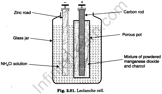
- Depolariser. Mixture of powdered manganese dioxide (MnO2) and charcoal (C). Charcoal powder makes MnO2 electrically conducting.
- Electrodes
(i) Negative electrode is an amalgamated zinc (Zn) rod dipped in electrolyte.
(ii) Positive electrode is carbon rod immersed in depolariser taken in a porous pot.
(b) Working. The reactions are :
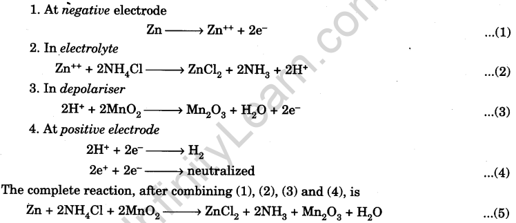
The electromotive force (e.m.f.) of the cell is 1.4 V. It can supply an electric current of 0. 25 A. Its internal resistance is about 1.2 Q.
(c) Merits. The e.m.f. is large (1.4 V). Hence, it is used in circuits where intermittent large current is required. It is very useful in electric bells, telephones and for balancing experiments where a large current is required for a short time only.
(d) Demerits (defects). It suffers from a defect, called polarisation. Though MnO2 acts as depolariser, but its action is slow. The polarisation is fast. Hydrogen gas accumulates on positive electrode.
(e) Applications. Due to partial polarisation, the cell gives large current for a short time only. Hence, it is used in electric bell and telephone circuits etc.
In laboratory, it is used in balancing circuits where a constant supply of current is not needed.
(f) Resting the cell. When the cell is put in ‘open circuit’ for few minutes, the accumulated hydrogen gas escapes from positive electrode. The cell regains its original e.m.f.
Daniel cells
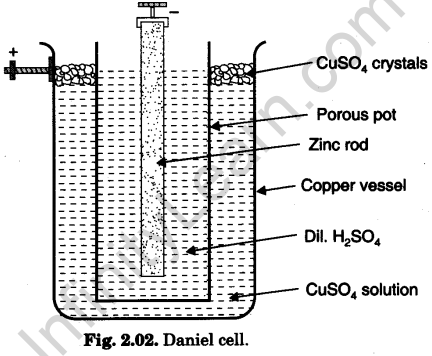
(a) Construction: Its components are shown in Fig. 2.02.
- Container: Copper vessel.
- Electrolyte: Dilute sulphuric acid (H2SO4) (or acidulated zinc sulphate-ZnSO4 solution).
- Depolariser: Saturated copper sulphate (CuSO4) solution.
- Electrodes:
(i) Negative electrode is amalgamated zinc rod immersed in electrolyte taken in a porous pot.
(ii)Positive electrode is copper vessel itself containing depolariser.
(b) Working: The reactions are :
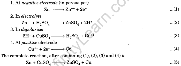
The electromotive force (e.m.f.) of the cell is 1.1 V. It can supply an electric current of 0.1 A. Its internal resistance is rather high.
(c) Merits: Since its e.m.f. and internal resistance remain fairly constant, the cell gives fairly constant current. Hence, it can be used in place of a standard cell where a weak but steady current is required.
(d) Demerits: (defects)
- It suffers from a defect, called polarisation. Though CuSO4 acts as depolariser,
but its action is slow. - The e.m.f. of the cell is very small (1.1 V only).
- The cell has to be dismantled, when not in use, otherwise Zn rod will be eaten by H2SO4 electrolyte.
(e) Applications: The cell gives a weak but steady current. Hence, it can be used in place of a standard cell (which is costly).
In laboratory, it is used in those circuits where a steady though weak current is required and costly standard cell is not available.
Dry cells
(a) Construction: Components of dry cell are shown in Fig. 2.03.
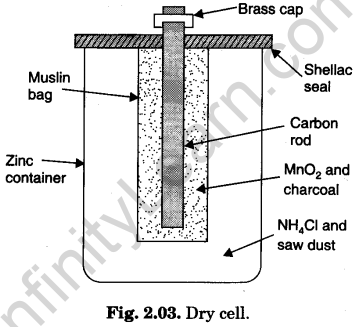
- Container: Zinc cup.
- Electrolyte: Moist paste of ammonium chloride (NH4Cl) containing some zinc chloride (ZnCl2) contained in zinc cup.
- Depolariser: MnO2and powdered charcoal (C) wrapped in porous cloth. The charcoal is used to increase the conductivity.
- Electrodes:
(i) Negative electrode is zinc cup itself containing electrolyte.
(ii) Positive electrode is carbon rod immersed in depolariser packed in porous cloth.
(b) Working: The reactions are :
These are the same as in Leclanche cell.
In fact, a dry cell is a portable form of Leclanche cell.
The electromotive force (e.m.f.) of the cell is 1.45 V. Its internal resistance is very small (about 0.2 ohm).
(c) Merits: It is compact and portable.
(d) Demerits: Same as in Leclanche cell.
(e) Application: Being portable, it is used in torches, transistor, radios, door bells, etc.
Lead (acid) accumulator
It is also called Lead sulphuric acid cell.
(a) Construction: Its components are shown in Fig. 2.04 :
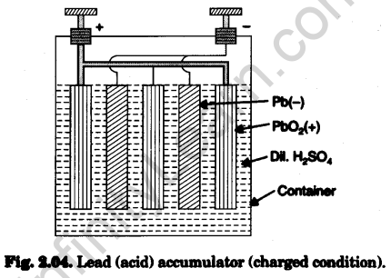
- Container. A glass or Bakelite case.
- Electrolyte. Dilute sulphuric acid (H2SO4).
- Electrodes. These consist of alternately parallel grid like plates of lead dioxide PbO2 (oxidised from PbO) which form positive electrode and spongy lead Pb (re¬duced from PbO) which form negative electrode.
These alternate plates are insulated from each other by porous separators made of wood, rubber, plastic or glass fibre.
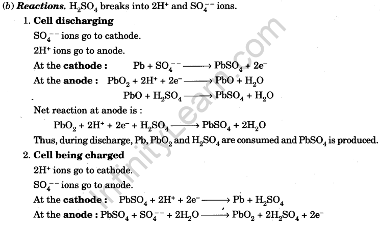
Thus, during charging, lead sulphate is consumed to give Pb, PbO2 and H2SO4. The active materials consumed during discharge are retrieved back during charging.
(c) Working:
- During discharge, each plate is converted into lead sulphate, sulphuric acid is consumed and water is produced. Electrolyte density becomes 1.12 and e.m.f. falls to 1.8 V, when cell is fully discharged.
Further discharging (over discharging) is harmful to the cell as then PbSO4 formed is insoluble (sulphating of plates). The cell can not be recharged. - During recharge, by passing a direct current, the reactions become reversed. Electrolyte density rises to 1.28 which is maximum. The e.m.f. becomes 2.1 V.
Further charging (over charging) will concentrate electrolyte which can eat up the plates.
(d) Merits: E.m.f. of each cell is 2.05 V and internal resistance is very low. Normally, a battery has six such cells in series to make a 12 V car battery. Due to low internal resistance, high currents can be drawn from the battery.
(e) Demerits: (defects)
- It is delicate, because it becomes damaged by over-charging or over-discharging.
- It is heavy due to lead plates.
- Its e.m.f. is small.
(f) Applications:
- They are used in car batteries or amplifier batteries.
- Being heavy and delicate they are not suitable for laboratory purposes, where chances of damage are fairly high.
Nickl- iron (alkali) accumulator
It is also called nife (Ni-Fe) cell.
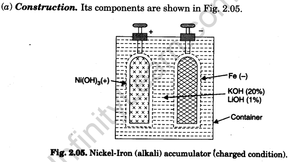
- Container. Steel vessel (Nickelled cold-rolled sheet steel box welded at the seams).
- Electrolyte. 20% solution of KOH with 1% lithium hydroxide having specific gravity 1.19 (Lithium hydroxide increases capacity of the cell by about 10%).
- Electrodes
(i) The negative electrode consists of perforated nickelled-steel grids ; filled ini¬tially with iron-oxide and a trace of yellow mercury oxide (which increases both the conductivity and the capacity of the cell).
(ii) The positive electrode consists of perforated nickelled-steel tubes filled ini¬tially with alternate layers of nickel hydroxide and metallic nickel in thin flakes, to make it conducting.
The container has a number of such electrode-pair pockets assembled inside it.
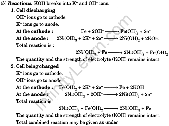

(c) Working: As is clear from the reactions, the electrolyte is neither consumed during discharging nor produced during charging and its strength remains intact. Hence, the cell is not damaged by over-discharging or over-charging.
The e.m.f. of fully charged cell is 1.35 V.
(d) Merits:
- It is not delicate because it is not damaged by over-charging or over-discharging.
- It is light because electrode metals are light.
- It can withstand heavy current during charge and discharge.
- It is very strong and durable.
- It can be left discharged for a long time without fear of getting damaged.
(e) Demerits: (defects)
- It is costlier than lead accumulator.
- Its e.m.f. is low, only 1.35 V.
- Its e.m.f. falls rapidly, as current is drawn.
(f) Applications. Being light and non-delicate, they are suitable for laboratory purposes, even inspite of high cost.
Battery and Battery eliminator
- Battery. A combination of cells is called a battery. A car battery has six lead (acid) accumators in series. It provides 12 volts (Fig. 2.06).
- Battery Eliminator. It is a low voltage rectifier in which 220 V A.C. is converted into low voltage like, 2 V, 4 V, 6 V, 8 V, 10 V and 12 V D.C. It is used in laboratories as a substitute for cells and batteries. It is available in different ranges. It needs no charging, which gives’it, a distinct advantage over other usual sources of e.m.f.
Electric circuit
Continuous path along which an electric current flows, is called electric circuit. The current flows only when the circuit is closed.
Keys
A key is an electrical accessory used in electric circuits to start and stop current in the circuit.
The different types of the keys are described as follows :
1. One-way key
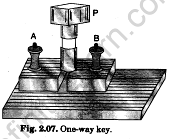
It has two thick brass blocks fixed on an ebonite base. The blocks are separated from each other by a cylindrical air gap. Terminals (binding screws) A and B are provided of the outer ends of the brass blocks. A tapered brass plug P can be tightly fitted into the cylindrical air gap (Fig. 2.07). The key is connected in series in a circuit. When the current is required to be started in the circuit, the plug is inserted in the gap. When the current is to be stopped, the plug is pulled out. The plug is inserted and removed with a screw motion.
2.Two-way key
It has one long (main or common) brass block and two small brass blocks perpendicular to it, fixed on an ebonite base. The three blocks form the letter F. There are two cylindrical air gaps between the main and the two small blocks. Three terminals (binding screws) are provided, one with each block.
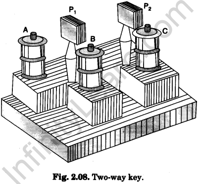
Tapered brass plugs can be tightly fitted into the cylindrical air gaps (Fig. 2.08). Terminal on main block is connected to the common arm of a circuit. Terminals on small blocks are connected to two branches of the circuit.
It is used in electric circuit for following purposes :
(i) to include and exclude the source of e.m.f.
(ii)to make current flow in the circuit from two different sources of e.m.f. when required.
(iii) to make current flow in different required parts of the circuit.
3.Tapping key
It has a metallic strip, whose one end is screwed on an ebonite base over a metallic block. Its other free end is provided with a knob. There is a metallic projection fixed on the ebonite base under the other end of the strip. The metallic block and the metallic projection are connected to two terminals (binding screws) (Fig. 2.09). The key is connected in series in a circuit.
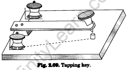
When the knob at the other end of the strip is pressed down, the strip makes contact with the metallic projection. Circuit becomes closed and current starts in the circuit.
When the pressure on the knob is removed the strip moves up. Circuit becomes open and current stops.
It is used in a circuit, when current is to be passed for a short interval of time.
4. Reversing key
It has two arc like metallic strips fixed on an ebonite base diametrically opposite to each other. These strips are provided with terminals (binding screws) A and B
An ebonite arm capable of rotation about a central vertical axis, has terminals C and D fixed at its two ends. These top metal¬lic terminals end downwards into metallic brushes making contact with the strips.
The key is used for reversing electric current in a circuit. The source of current is connected between one pair of terminals (A-B or C-D) and the circuit is connected between the other pair. In the position of the arm (shown in diagram) C makes contact with A and D with B. Current flows in circuit is one direction. When the arm is rotated sufficiently, C makes contact with B and D with A. Direction of current in the circuit becomes reversed.
Resistors
Resistors are used in electric circuits to control the current. The various forms of resistors used in laboratory experiments are :
1. Resistance coil
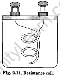 A resistance coil is usually made from wire of a material whose temperature coefficient of resistance is low i.e., whose resistance does not change much with change in temperature and high resistivity. The alloy materials are selected for making the wire are constantan, manganin, eureka, and german silver.
A calculated length of the insulated wire is taken which can give required resistance. It is double-folded and then wrapped on a wooden bobbin or reel (Fig. 2.11). The bobbin is enclosed in an ebonite box. The two free ends of the wire are soldered to the two metallic terminals (binding screws) provided at the top of the ebonite box.
The wire is double-folded in order to avoid induction effect (read chapter on electromagnetic induction).
2.Resistance box
A resistance box contains a set of resistance coils of known values. These resistance coils are arranged in series inside a rectangular wooden box. [Fig. 2.12 (a)].
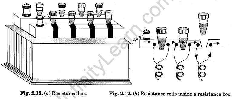
The rectangular wooden box has an ebonite top. On this ebonite top, the brass blocks are fixed, making an U-shape. Each two adjacent blocks have a cylindrical air gap between
them (just as in keys). The blocks are screwed with long screws projecting out of the width of the top. –
Resistance coils have wires of known resistance values wrapped over wooden bobbins. The two free ends of the wire of a coil are soldered to the two projecting screws, on each side of a gap, under the ebonite top. [Fig. 2.12 (b)]. The value of the resistance of each coil is written (marked) on the top by the side of the corresponding gap.
The coil resistance have values 1, 2, 5, 10, 20, 20, 50, 100, 200, 200, 500, 1000, 2000, 2000 and 5000 ohms in bigger boxes and only upto 500 ohms in smaller boxes. 1 ohm and 5000 ohm (or 500 ohm) coils are near the ends where terminals (binding screws) are provided. A gap marked INF (means infinite) is provided at the bend of U form. This gap has no wire and is similar to one-way key.
The box is put in series in a circuit in which known resistances are to be introduced. When tapered plugs are inserted in all the gaps, current directly passes through the brass blocks. It does not pass through any resistance coil and the box is said to have introduced no resistance in the circuit.
When plug is taken out, the gap becomes open. Then the current has to pass through the resistance coil connected across (parallel to) that gap. Its resistance becomes introduced in the circuit. If more than one gap is open, the resistances of all the coils across those gaps become added. Since the coils are connected in series, the total resistance introduced in the circuit becomes sum of the resistances of the coils connected across the open gaps. Using different gaps, any resistance (in integral value of ohms) can be introduced in the circuit.
While using a resistance box, following important points must be kept in mind :
(i) Keep the plugs tight in the gaps.
(ii) Remove and insert a plug with a screw motion.
(iii) Do not pass large currents through the coils (to avoid burning of resistance coils).
3. Rheostat
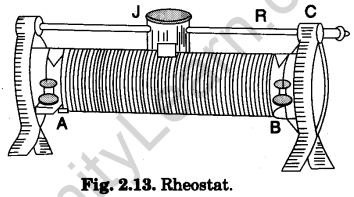 It is a variable resistance device and is commonly used for adjusting the strength of electric current in an electric circuit.
It is made by wrapping a long wire of constantan round a non-conducting ceramic cylinder as shown in Fig. 2.13. The two ends of the wire are connected to the two terminals (binding screws) A and B. A thick metallic rod R is attached to the frame above the cylinder parallel to its length. A slider or a jockey J can slide over it. The jockey itself makes contact with the rod and the metallic strips under it make contact with the wire wrapped over the cylinder (core).
Its maximum resistance (resistance of whole wire) and the maximum amount of current, it can bear, are printed on a tag fitted to it (e.g., 50 ohm-1.0 A).
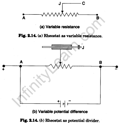
A rheostat can be used in two ways :
(i) as a variable resistance
(ii) as a potential divider.
The two arrangements are shown in Fig. 2.14 (a) and Fig. 2.14 (6) given as follows : When the rheostat is used as a variable resistor than any one terminal A or B of rheostat is connected to one end of circuit in series and terminal C is connected to other end of the circuit (as shown in Fig. 2.14(a)) When the rheostat is used as a potential divider then current is passed through rheostat by connecting a battery directly between A and B. There is a fall of potential from one end to other end of the rheostat. Now the one end of circuit is connected to A or B terminal and other end of circuit is connected to C terminal of rheostat.
In using the rheostat, care should be taken, never pass the current beyond the maximum current recommended otherwise the rheostat will be overheated and burnt.
Galvanometer
A galvanometer is a device (instrument) used for detecting feeble electric currents in circuits.
Moving coil Galvanometer
In laboratory we commonly use a pivoted coil pointer type moving coil galvanometer, called Weston galvanometer (Fig. 2.15).
It consists of a high, laminated, horse-shoe magnet with concave pole faces to provide a radial magnetic field. A coil of thin insulated copper wire wrapped over a copper frame is mounted on two jewelled pivots symmetrically between thd pole faces. The motion of the coil is controlled by two attached hair springs, one above and the other below the coil. These hair
springs also serve as lead and make contact with two terminals (binding screws) provided at the top of the bakelite frame. An aluminium pointer is attached perpendicular to the coil. The free end of the pointer moves over an arc like scale. The scale has zero (0) in the middle and equal number of divisions (25 or 30 divisions, 1 div = 1°) on either side of the central zero. The pointer end stays at zero when there is no current in the circuit.
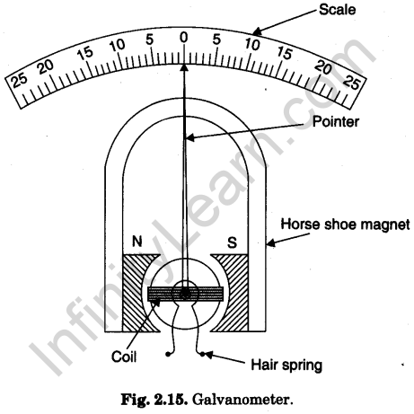
The galvanometer is connected in series in the circuit in which current is to be detected. The current passes through the coil pivoted in the magnetic field. The coil experiences equal, parallel and opposite forces on its arms which form a couple. The couple rotates the coil which makes the pointer move on the scale. The deflection (measured as number of divisions) is proportional to the current passed. The galvanometer is quite sensitive and gives full scale deflection even for a small current (say 1 milliampere).
Ammeter
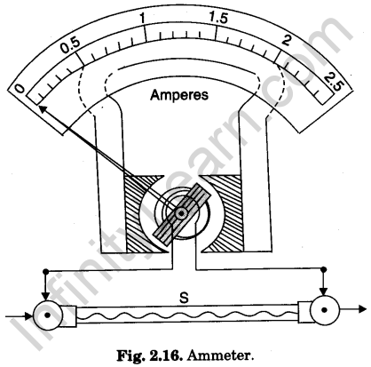
An ammeter is a small resistance device (instrument) used for measuring electric currents in circuits. For this purpose it is put in series with the circuit in which the current is to be measured.
A galvanometer is converted into an ammeter by connecting a suitable low resistance, called shunt, across its coil. The shunt resistance (S) is connected to the coil internally (Fig. 2.16). Thus an ammeter is actually a low resistance galvanometer.
The scale of an ammeter is graduated to read the current directly in amperes (A). The full name of an ammeter is ampere-meter. An ammeter measuring current in milli-amperes (10-3 A or mA) is called milliammeter. A micro-ammeter measures current in micro-amperes (10-6 A or μA).
Voltmeter
A voltmeter is a high resistance device (instrument) used for measuring electric potential difference between two points in a circuit. For this purpose, it is put in parallel with that branch of circuit, at the ends of which the potential difference is to be measured.
As a voltmeter has to be put in parallel in the circuit for measuring the potential difference, it must take very small current from the circuit for which it must have very high resistance. A galvanometer is converted into a voltmeter by connecting a suitable high resistance in series with its coil. The series high resistance (R) is connected to the coil internally (Fig. 2.17). Thus, a voltmeter is actually a high resistance galvanometer.
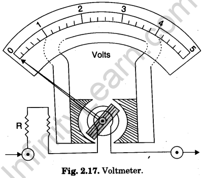
The scale of voltmeter is graduated to read the potential difference directly in volts (V). A voltmeter measuring potential difference in milli-volts (10-3 V or mV), is called milli-volt- meter. A micro-voltmeter measured potential difference in mirco-volts (10-6 V or μV).
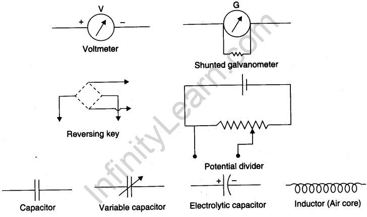
Symbols used for electrical components
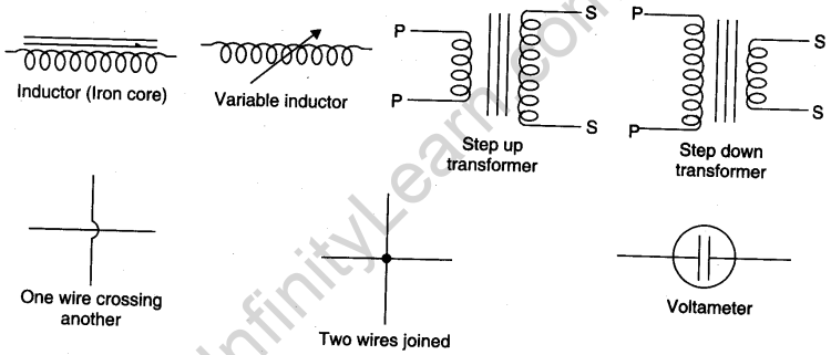
Viva Voce
Electric current
Question. 1. What is static electricity?
Answer. Electric charges at rest, present on the surface of a body, constitute static electricity.
Question. 2. What is current electricity?
Answer.Electric charges flowing in a conductor, constitute current electricity.
Question. 3. Define electric current.
Answer. The time rate of flow of electric charge i.e., electric charge flowing per second at a cross¬section of conductor, is called electric current. It is represented by the symbol I.
Question. 4. Give expression for electric current.
Answer.
![]()
Question. 5. Give unit of electric current.
Answer. The unit of electric current is ampere (A).
Question. 6. Define ampere as unit of electric current.
Answer. Current through a cross section of conductor is one ampere, if one coulomb charge flows through that cross section in one second.
![]()
Question. 7. Give direction of electric current.
Answer. The current is a scalar quantity but its conventional direction is the direction of flow of a positive charge. The direction of conventional current is opposite to the electronic current (current due to flow of electrons).
Question. 8. What is cell?
Answer. A cell is a device by which electric energy is generated due to chemical action taking place inside it.
Question. 9. What is a battery?
Answer. A battery is a combination of cells in series. The e.m.f. of the battery-is the sum of the e.m.fs. of the cells.
Question. 10. What is a primary cell?
Answer. Cell which directly gives electrical energy from chemical energy, is called a primary cell. This cannot be recharged.
Question. 11. What is a secondary cell?
Answer. Cell which stores electrical energy as chemical energy and returns it back as electrical energy, is called a secondary cell. This can be recharged.
Question. 12. Name common primary cells.
Answer. The common primary cells are :
- Leclanche cell.
- Daniel cell
- Dry cell.
Question. 13. Name common secondary cells.
Answer.The common secondary cells are :
(1) Lead (Acid) Accumulator (2) Ni-Fe (Alkali) Accumulator.
Question. 14. Describe components and working of primary cells. Discuss their merits and demerits.
Answer. (Read Arts. 2.04, 2.05 and 2.06).
Question. 15. What is partial polarisation of a Lechanche cell?
Answer. In Leclanche cell, polarisation is fast but depolarisation is slow. It makes the cell polarised after some time. This is called partial polarisation.
Question. 16. What happens in partial polarisation?
Answer. Hydrogen gas bubbles accumulate on positive electrode and forms an insulating layer over it.
Question. 17. What is the effect of partial polarisation on the working of the cell?
Answer. The cell gives a strong current only for a short time. Then current becomes weak.
Question. 18. How the partial polarisation of the cell is removed?
Answer. The cell is given rest by keeping it in open circuit for few minutes.
Question. 19. How does the ‘resting’ help in removal of partial polarisation?
Answer. The accumulated hydrogen bubbles escape from the positive electrode. The cell regains its original e.m.f.
Question. 20. For what applications, is the Leclanche cell suitable?
Answer. The Leclanche cell is suitable where large electric current is required for a short time only e.g., electric bells, telephones etc.
Question. 21. Which primary cell can be used if a standard cell is not available?
Answer. A Daniel cell can be used if a standard cell is not available.
Question. 22. What makes a Daniel cell a substitute for a standard cell?
Answer. Daniel cell gives small but steady current for sufficiently long time. Hence, it becomes a cheap substitute for a standard cell.
Question. 23. Where is a dry cell used?
Answer. A dry cell is used in portable devices like torches and transistor radios.
Question. 24. Describe components, reaction and working of secondary cells. Discuss their merits and demerits.
Answer. (Read Arts. 2.07 and 2.08).
Question. 25. Why is a lead accumulator delicate?
Answer. It is delicate because it gets damaged by over-discharging and over-charging.
Question. 26. Why is a lead accumulator heavy?
Answer. It is heavy because its electrodes are lead plates.
Question. 27. Why is a lead accumulator not suitable for laboratory purposes?
Answer.
- Since it is heavy, it is difficult to move it from table to table.
- Since it is delicate, a slight carelessness on the part of the experimenter may damage it.
Question. 28. Why is an alkali accumulator not delicate?
Answer. It is not delicate because it does not get damaged by over-discharging and over¬charging.
Question. 29. Why is an alkali accumulator light?
Answer. It is light because its electrode metals are light.
Question. 30. Why is alkali accumulator suitable for laboratory purposes?
Answer.
- Since it is light, it can easily be moved from table to table.
- Since it is not delicate, there is no fear of its damage by carelessness of an experimeter.
Question. 31. Give economical comparison of primary and secondary cells.
Answer. Primary cells are cheap in investment but become costly due to replacement. Their running cost is high.
Secondary cell are costly in investment but remain cheap in maintenance. Their run¬ning cost is low. Secondary cells supply more current than primary current because of small resistance for the same e.m.f.
Electric circuit and key
Question. 32. Define electric circuit.
Answer. Continuous path along which an electric current flows, is called electric circuit.
Question. 33. When does a current flow an electric circuit?
Answer. Current flows in an electric circuit only when circuit is closed or switched on.
Question. 34. What is short circuit of a cell? How does it harm the cell?
Answer. A cell becomes short-circuited, when its terminals are directly connected. A large cur¬rent flowing from the cell may damage it.
Question. 35. What is a key?
Answer. A key is airelectrical accessory used in electric circuits to start and stop current in the circuit.
Question. 36. What is an open circuit?
Answer. A circuit becomes an open circuit, when the key is out. No current flows in an open circuit.
Resistor, resistance box and rheostat
Question. 37. What is a resistor?
Answer. It is an electrical component used in electric circuits to control the current.
Question. 38. In what different forms, resistors are used in electric circuits?
Answer.
- With fixed known value of their resistance, they are used as resistance coils or in resistance boxes.
- With variable unknown value of their resistance, they are used as rheostats.
Question. 39. Why is wire in a resistance coil or a resistance box double folded?
Answer. It is done to avoid induction effect.
Question. 40. How are the resistances of different values obtained in a resistance box?
Answer. The resistance values are increased by taking longer and thinner wire.
Question. 41. What are dimensions of the wire used for providing infinite resistance?
Answer. No wire is used for this purpose. Open air gap provides infinite resistance.
Question. 42. Which material is suitable for construction of standard resistances for resist¬ance box?
Answer. Materials used are :
- Constantan (or Eureka) (Cu 60%, Ni 40%)
- Manganin (Cu 83%, Mn 13%, Ni 4%).
Question. 43. What properties make a material suitable for standard resistances?
Answer. The suitable properties are :
- High specific resistance—lesser length of wire gives required resistance.
- Low temperature coefficient of resistance—the resistance does not change apprecia¬bly with change in temperature.
Question. 44. What is a rheostat?
Answer. It is a variable resistance device and is commonly used for adjusting the strength of electric current in an electric circuit.
Question. 45. How is a rheostat made?
Answer. Oxide coated manganin wire is wrapped over porcelain tube.
Question. 46. How does the slider make contact with the insulated wire?
Answer. Due to repeated motion of the slider, insulation from the wire becomes removed. Slider makes contact with the wire.
Question. 47. To what other application, a rheostat can b,e used?
Answer. A rheostat can be used as a potential divider [See Fig. 2.14 (b)].
Galvanometer,ammeter and voltmeter
Question. 48. What is a galvanometer?
Answer. It is an instrument, used for detecting feeble currents in an electric circuit.
Question. 49. What is an ammeter?
Answer. It is a low resistance device, used for measuring electric current in a circuit. It is connected in series in the circuit.
Question. 50. What is full name of an ammeter?
Answer. The full name is ampere-meter.
Question. 51. What is a voltmeter?
Answer. It is a high resistance device, used for measuring potential difference in a circuit. It is connected in parallel in the circuit.
Question. 52. What is ideal ammeter?
Answer. It is an ammeter whose resistance is zero.
Question. 53. What is ideal voltmeter?
Answer. It is a voltmeter whose resistance is infinity.
Question. 54. What are the required properties of an ammeter?
Answer. An ammeter must have a very small resistance (zero, if possible) and a large current carrying capacity.
Question. 55. What are the required properties of a voltmeter?
Answer. A voltmeter must have a very large resistance (infinite, if possible) and a very small current carrying capacity.
Question. 56. How is a galvanometer converted into an ammeter?
Answer. A galvanometer is converted into an ammeter by connecting a low resistance in parallel with the galvanometer coil (this parallel low resistance is called shunt).
Question. 57. Why is a galvanometer not suitable to work as voltmeter?
Answer. A galvanometer has less resistance and more current-carrying capacity from those required by a voltmeter.
Question. 58. How is a galvanometer converted into a voltmeter?
Answer.A galvanometer into converted into a voltameter by connecting a high resistance in seriece with the galvanomerer coil


