Table of Contents
Half-Wave Rectifier: A rectifier is an electrical device that acts like a magic electric tool. Its main job is to change wavy power into a smooth and straight flow. Picture it as a converter that takes the wavy power, known as alternating current (AC), and transforms it into a steady flow called direct current (DC).
This transformation happens using special gates called diodes, which only allow electricity to go in one direction. By doing this, the rectifier makes the power more dependable and suitable for our devices. So, think of a rectifier as a friendly helper for electricity, making it behave so that our gadgets and machines can easily understand and use it.
What Is Half Wave Rectifier?
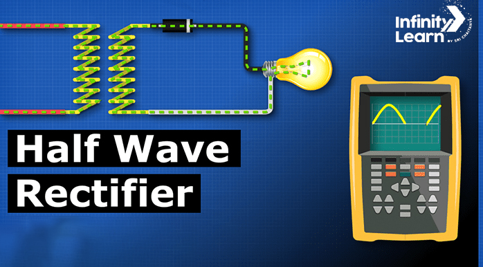
A Half-Wave Rectifier is an electrical converter, that changes wavy power into a simpler flow. It transforms alternating current (AC) into direct current (DC). Think of a Half-Wave Rectifier like a traffic controller known as a diode, a special tool in electronics. This diode only allows one part of the electricity wave to pass through – the part that goes up.
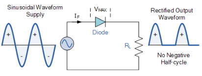
When the AC wave goes up and down, the half-wave rectifier permits only the upward part, the positive half, to pass through. The diode acts as a gate, enabling electricity to flow in one direction. This results in DC power going up and down, not perfectly smooth but still usable. We refer to this as pulsating DC.
Despite being a simple method for converting power, the half-wave rectifier introduces some ripples or gaps in its output. It is commonly employed in uncomplicated devices where a bit of irregularity in the power is acceptable. More sophisticated converters are utilised for applications requiring smoother and more efficient power.
Half Wave Rectifier Circuit
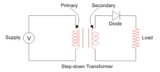
A half-wave rectifier circuit acts like a translator for electricity, turning wavy power into a simpler flow. Here’s how it does its job:
Components
- Transformer: It starts with a transformer that makes the electricity less strong.
- Diode: The main player is a diode, a special tool that lets electricity flow in one direction.
Given below is the half wave rectifier diagram
Working Of Half Wave Rectifier
AC Input
Visualise electricity as a wave going up and down, representing AC (alternating current).
Transforming Voltage
Envision a transformer adjusting the electricity’s strength, converting the high wave into a lower one.
Diode’s Role
Introduce a diode, acting like a one-way valve that allows electricity to flow only in one direction.
Positive Half-Cycle
During the upward part of the wave (positive half-cycle), the diode opens, permitting electricity to pass through.
Negative Half-Cycle
When the wave goes downward (negative half-cycle), the diode blocks the electricity, acting like a closed valve.
Output Signal
The outcome is a chopped-off part of the wave, forming the DC (direct current) output.
Average Strength
The DC output isn’t perfectly smooth; it’s an average of the chopped-off part, approximately 90% of the highest point.
Ripples
Since only a part of the wave is allowed, there are ripples or variations in the DC output, making it less steady than a constant current.
Half Wave Rectifier Waveform
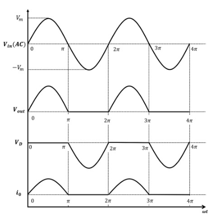
Formula of Half Wave Rectifier
The formula for the average or DC output voltage, (VDC) of a Half-wave Rectifier is given by:
VDC = Vmax/pie
Here:
– VDC is the average DC output voltage.
– Vmax is the maximum peak value of the input AC voltage.
In simpler terms, this formula helps calculate the average DC voltage that we get from a half-wave rectifier. It considers the highest point (peak) of the input AC voltage and provides an average value, taking into account the characteristics of the half-wave rectifier circuit.
Applications Of Half Wave Rectifier:
Battery Charging
A half-wave Rectifier is employed in basic battery chargers to transform household AC into the necessary DC for charging batteries.
Low-Power Devices
A half-wave Rectifier is used in simple devices where a smooth DC output isn’t crucial, emphasising simplicity.
Light Dimming
A half-wave Rectifier is integrated into certain lighting systems, particularly older designs, to control light intensity.
Heating Devices
A half-wave Rectifier is utilised in appliances like electric stoves and water heaters to convert AC to DC for heating elements.
Electroplating
A half-wave Rectifier plays a role in electroplating processes, providing the required direct current for metal coating.
Educational Tools
A half-wave Rectifier is frequently employed in educational settings to teach fundamental rectification and electronic circuit principles.
Signal Demodulation
Some AM radio receivers are utilized to demodulate audio signals from carrier waves.
Pulse Generators
A half-wave Rectifier is found in circuits requiring DC pulses, commonly used in various electronic applications.
Simple Power Supplies
A half-wave Rectifier is used in basic electronic devices and experiments where a consistent DC voltage is not critical.
Voltage Reference
A half-wave Rectifier is applied in circuits needing a voltage reference, where a smoother DC output is not the primary concern.
RF Signal Detection
A half-wave Rectifier is present in older radio receivers for converting RF signals into baseband audio signals.
Obsolete Applications
A half-wave Rectifier is less common in modern electronics, it is still found in some legacy or less demanding applications.
FAQs on Half Wave Rectifier
What is a Half-Wave Rectifier?
A half-wave rectifier is designed to convert alternating current (AC) into direct current (DC) by allowing only one-half of the AC waveform to pass through.
How Does a Half-Wave Rectifier Work?
The operation of a half-wave rectifier involves using a diode to permit only the positive half of the AC input signal to flow through. This results in a unidirectional current flow, generating a pulsating DC waveform.
What is the Efficiency of a Half Wave Rectifier?
The efficiency of a half-wave rectifier is relatively modest, typically between 40% to 50%. This is due to its utilisation of only half of the AC waveform, resulting in significant power loss.
Where is a Half-Wave Rectifier Used?
While less efficient, half-wave rectifiers find application in low-power devices such as small power supplies, battery chargers, and uncomplicated electronic circuits where the acceptable power loss is manageable.
What are the Disadvantages of a Half-Wave Rectifier?
Drawbacks of a half-wave rectifier include its lower efficiency, as it only utilises half of the AC waveform, leading to notable power loss. Additionally, it produces a pulsating DC output with a considerable AC component, which may not be suitable for specific electronic applications


