Table of Contents
Semiconductor Electronics Important Questions for CBSE Class 12 Physics Logic Gates, Transistors and its Applications
1.Junction Transistor A junction transistor is three terminal semiconductor device consisting of two p-n junctions formed by placing a thin layer of doped semiconductor ip-type or n-type) between two thick similar layers of opposite type. There are two types of transistor:
(i)n-p-n transistor Here, two segments of n-type semiconductor (emitter and collector) are separated by a segment of p-type semiconductor (base).
(ii)p-n-p transistor Here, two segments of p-type (termed as emitter and collector) are separated by a segment of n-type semiconductor (base).
2.Transistors Schematic representation

3.Transistor Action or Working of Transistor
(i)p-n-p Transistor
From given figure, we can see that, the emitter-base junction is forward biased. Collector-base junction is reverse biased.
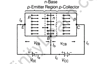
The resistance of emitter-base junction is very low. so the voltage of Vee (Veb) is quite small (i.e.,1.5 V). The current in p-n-p transistor is carried by holes and at the same time their concentration maintained But in external circuit the current is due to the flow of electrons.
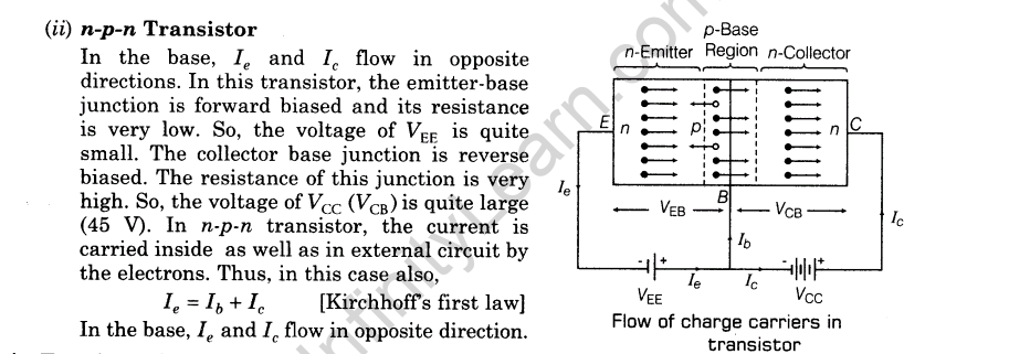
4.Transistors Configuration
(i)Common Base (CB) mode.
(ii)Common Emitter (CE) mode.
(iii)Common Collector (CC) mode.
5.Characteristics of a Transistor The graphical representation of the variations among the various current and voltage variables of a transistor are called transistor characteristics

The common base characteristics of a transistor are of two types:
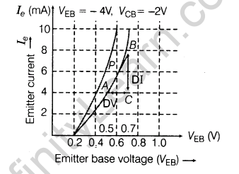
(a) Emitter or Input Characteristics A graphical relation between the emitter voltage and emitter current at constant collector voltage, is called emitter or input characteristics. The graph is plotted between emitter current and corresponding emitter voltage
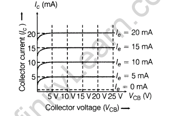
(b)Collector or Output Characteristics A graphical relation between the collector voltage and collector current at constant emitter current, is called collector or output characteristics .The graph is plotted between collector current and corresponding collector voltage.
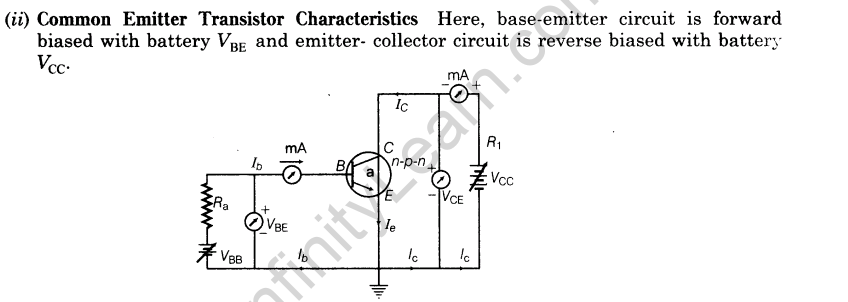
These two characteristics can be studied as shown below:
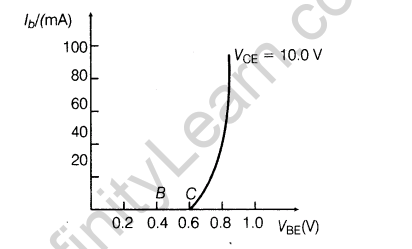
(a) Emitter or Input Characteristics. A graphical relation between the emitter voltage and the emitter current by keeping collector voltage constant is called input characteristics of the transistor

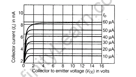
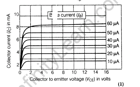
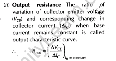
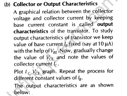
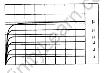
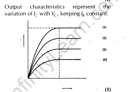
(b) Collector or Output Characteristics A graphical relation between the collector voltage and collector current by keeping base current constant is called output characteristics of the transistor


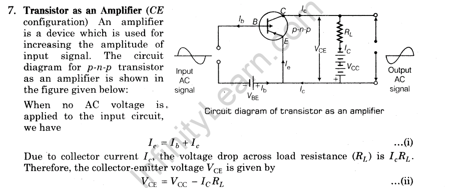
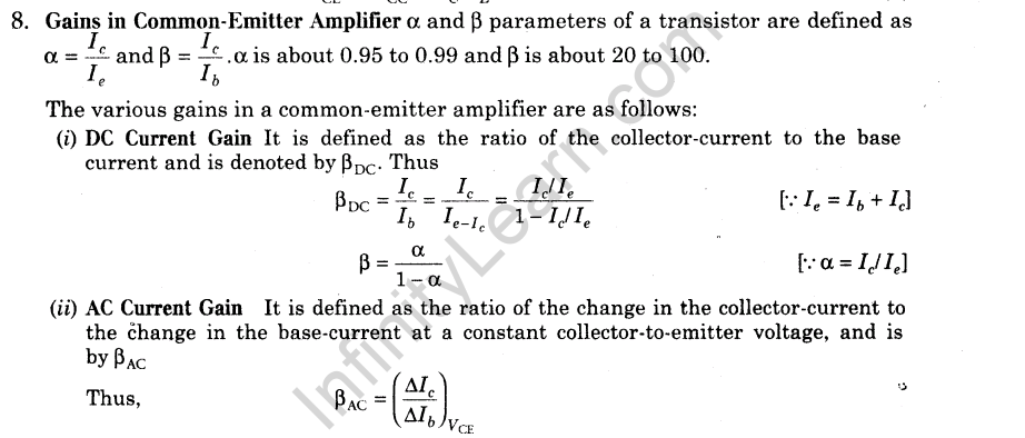

11.Analog Circuits Circuits use signals (current or voltage) in the form of continuous, time-varying voltage or current.
12.Digital Circuits Circuits use two discrete level of current or voltage which are termed as binary signals. These two values are represented as 0 and 1 (low or high i.e.ON or OFF)
13.Logic Gate These are building blocks of electronic circuits. In logic gates, there exist a logical relationship between output and input(s).
14.Truth Table It is a table that shows all possible input combinations and the corresponding output combinations for a logic gate.
Boolean Expression The expression shows the combination of two Boolean variables that results into a new Boolean variable is known as Boolean expression.
15.Basic Gates There are three basic gates:
(i) OR Gate Boolean expression of OR gate is given as Y = A + B.
(a) It has two or more inputs and one output.
(b) In this gate, if any one of the input or all the inputs are 1, then output is 1.


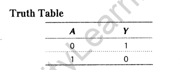
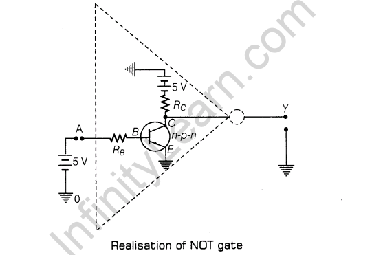


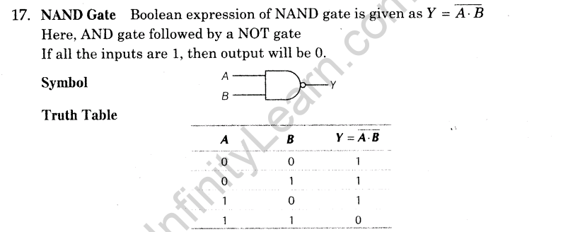

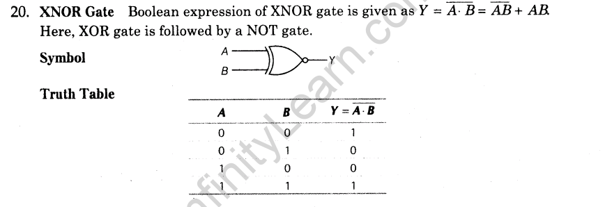
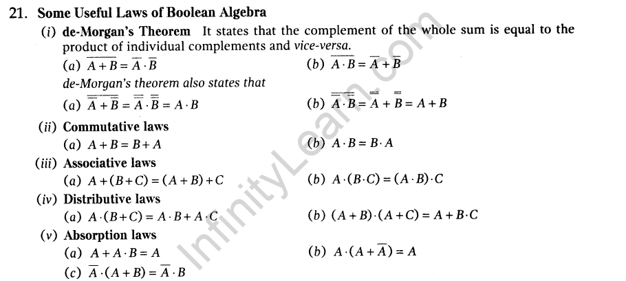
Previous Year Examination Questions
1 Mark Questions
1.In a transistor, doping level in base is increased slightly. How will it affect
(i)collector current and
(ii)base current? [Delhi 2011]
Ans.(i) Collector current decreases.
(ii) Base current increases
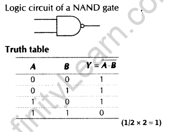
2.Draw the logic circuit of a NAND gate and write its truth table.[Foreign 20113]
Ans.
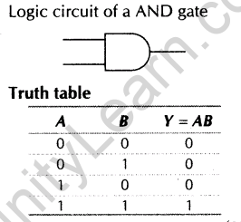
3.Draw the logic circuit of AND gate and write its truth table.[Foreign 2011]
Ans.
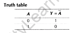
4.Draw the logic circuit of NOT gate and write its truth table.[Foreign 2011]
Ans.

Ans.
Ans.
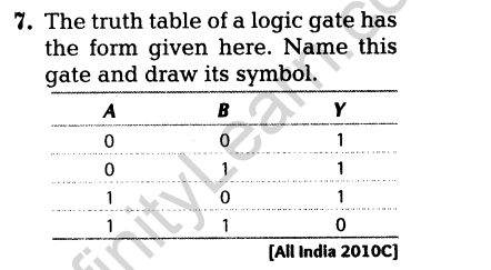
Ans.

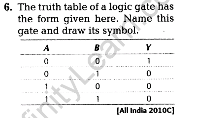
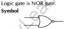
8.Give the logic symbol of NOR gate.[All India 2009]
Ans.

9.Give the logic symbol of NAND gate. [All India 2009]
Ans.

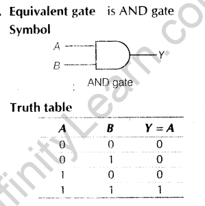
10.Give the logic symbol of AND gate.[All India 2009]
Ans.

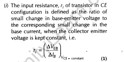
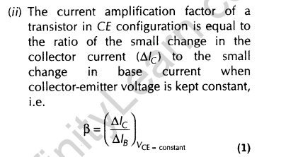
11.Define current amplification factor in common-emitter mode of transistor. [Delhi 2009 C, All India 2010 C]
Ans.

2 Marks Questions
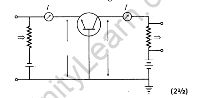
12.Draw a circuit diagram of n-p-n transistor amplifier in CE configuration. Under what condition does the transistor act as an amplifier? [All India 2014]
Ans.Circuit diagram of n-p-n transistor amplifier in CE configuration is given below
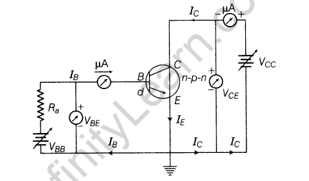
The condition for the amplifier to work is that the base-emitter junction should be forward biased and collector-base junction should be reversed biased
Ans.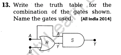
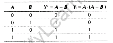
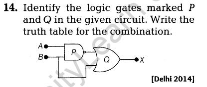
Ans.
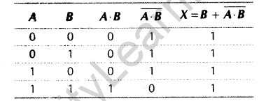
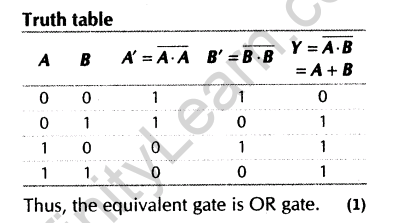
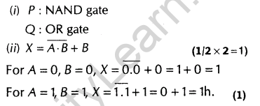
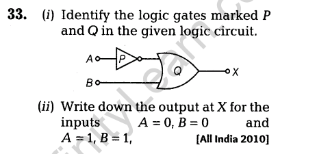
The logic gates are Pis NAND gate and Q is OR gate.
The truth table is given as shown in below:
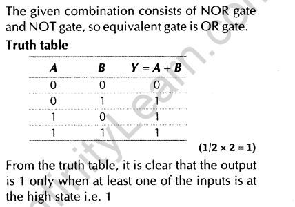
15.The outputs of two NOT gates are fed to a NOR gate. Draw the logic circuit of the combination of gates. Give its truth table. Identify the gate represented by this combination.[Delhi 2014 C]
Ans.

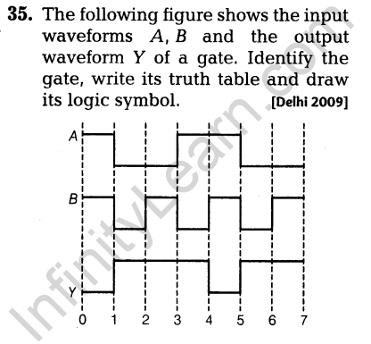
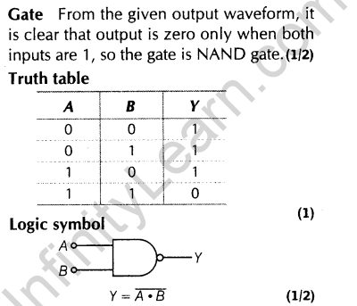
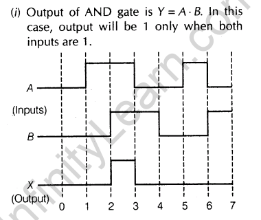
16.The input wave forms A and B and the output waveform Y of a gate are shown below. Name the gate it represents, write its truth table and draw the logic symbol of this gate.
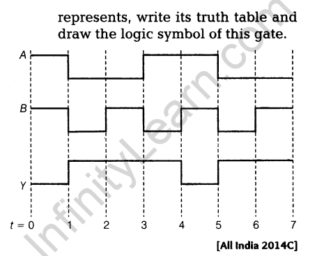
Ans.

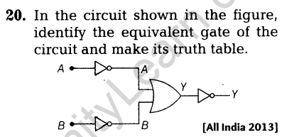
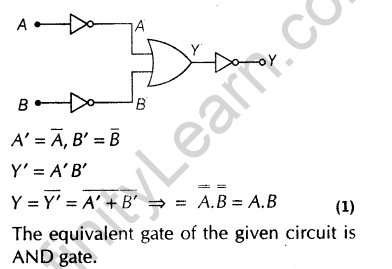
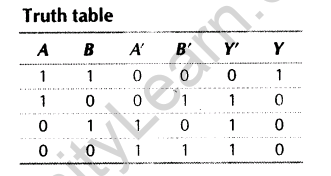
17. Identify the equivalent gate represented by the circuit shown in the figure. Draw its logic symbol and write the truth table.
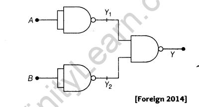
Ans.

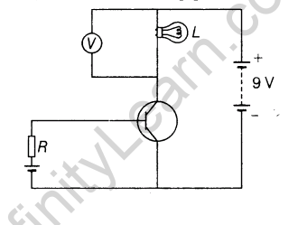
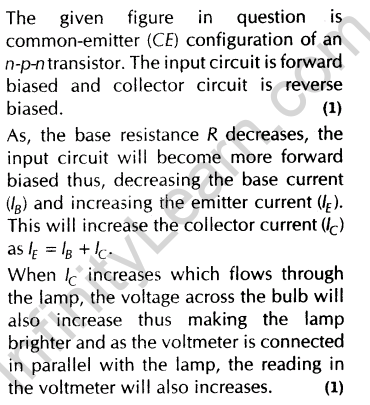
18.In the given circuit diagram, a voltmeter V is connected across a lamp L. How would
(i)the brightness of the lamp and
(ii)voltmeter reading V be affected if the value of resistance R is decreased? Justify your answer.
Ans.
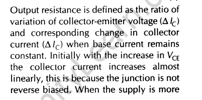
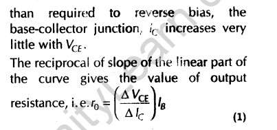
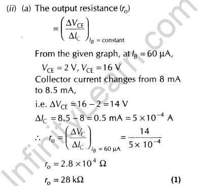
19.Draw a typical output characteristics of an n-p-n transistor in CE Show how these characteristics can be used to determine output resistance?[All India 2013]
Ans.

Ans.
Ans.
Ans.
23.Describe briefly with the help of a circuit diagram, how the flow of current carriers in a p-n-p transistor is regulated with emitter-base junction in forward biased and base-collector junction in reverse biased. [All India 2012]
Ans.
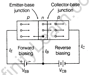
Heavily doped emitter is subjected to electric field by emitter-base battery and consequently, holes gets drifted towards collector through thin and lightly doped base region. Nearly 5% hole, which drifted from emitter combined with electron in base region and remaining nearly 95% hole reaches to collector under the influence VCE.
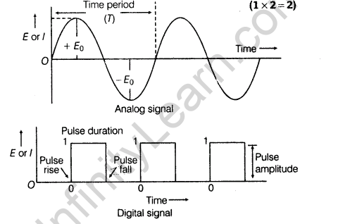
24.Distinguish between analog signal and digital signal. [All India 2012]
Ans.A signal in which current or voltage changes continuously with the time is called analog signals. A signal in which current or voltage can take only two discrete values is called a digital signal.
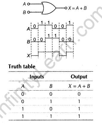
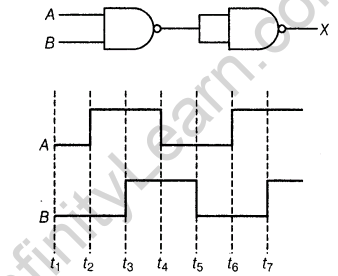
25.Draw the output waveform at X using the given inputs, A and B for the logic circuit shown below. Also, identify the logic operation performed by this circuit
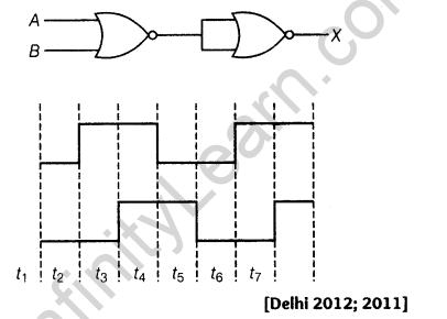
Ans.Equivalent gate is OR gate. If input A or B or both are 1, then the output of OR gate is 1.
Boolean expression of OR gate is given as A + B = X
Logic symbol of OR gate and the output waveform as shown below
26.In the given circuit, a voltmeter V is connected across lamp L What changes would you observe in the lamp L and the voltmeter V if the value of resistor R is reduced?
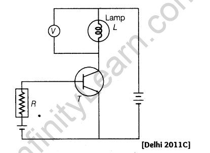
Ans.Lamp glows brighter and voltmeter reading increases with the decrease of R. Input current increase which in turn by transistor action lead to increase collector current. This makes lamp brighter and hence, voltmeter reading goes up.
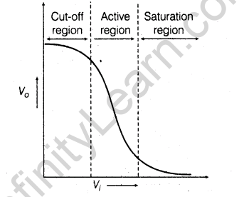
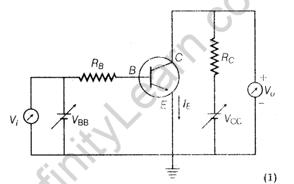
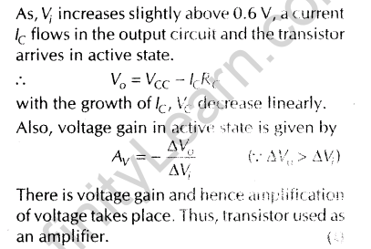
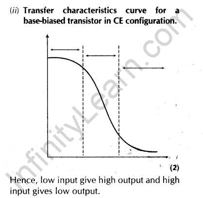
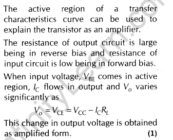
27.Draw the transfer characteristic curve of a base-biased transistor in CE Explain clearly how the active region of the V0 versus Vi. curve, in a transistor is used as an amplifier? [Delhi 2011]
Ans.The transfer characteristic curve of base biased transistor in CE configuration as shown below:
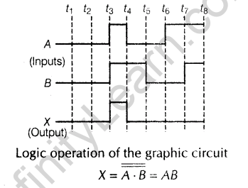
28.Draw the output waveform at X using the given inputs, A and B for the logic circuit shown below. Also, identify the logic operation performed by this circuit.[Delhi 2011; 2008]
Ans.

29.Write the truth table for the logic circuit shown below and identify the logic operation performed by this Circuit. [Delhi 2011]
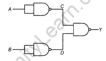
Ans.
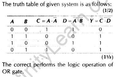
30.Identify the logic gates X and Y in the figure. Write down the truth table of output Z for all possible inputs A and [All India 2011 c]

Ans.
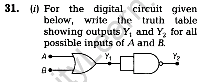
(ii) Show output waveform for all possible inputs of A and B.[All India 2011 C]
Ans.
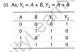
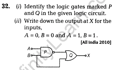
Ans.
Ans.


Ans.
Ans.
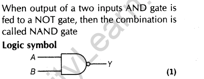
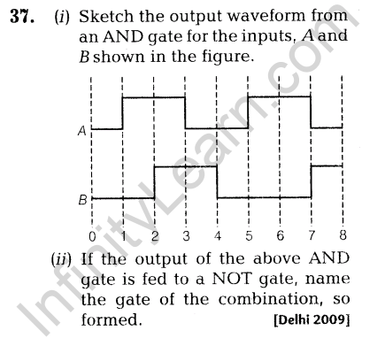
36.The output of a 2-input AND gate is fed to a NOT gate. Give the name of the combination and its logic symbol. Write down its truth table.[Foreign 2008, Delhi 2009]
Ans.

Ans.
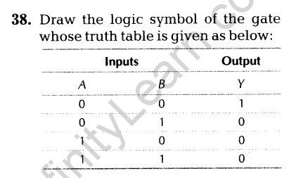
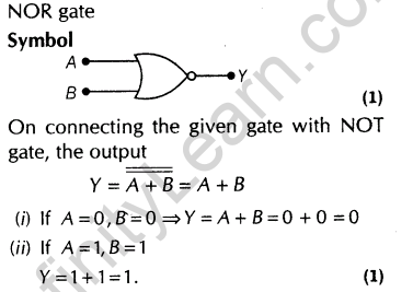
If this, logic gate is connected to NOT gate, what will be the output when
(i)A = 0, B = 0 and
(ii)A = 1 B = 1?
Draw the logic symbol of the Combination.[Foreign 2009]
Ans.
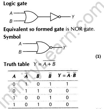
39.A logic gate is obtained by applying output of OR gate to a NOT gate.Name the gate so formed. Write the symbol and truth table of this gate.[Foreign 2009]
Ans.
40.A logic gate is obtained by applying output of AND gate to a NOT gate. Name the gate so formed. Write the symbol and truth table of this gate.[Foreign 2009]
Ans.

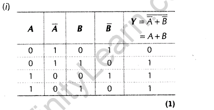
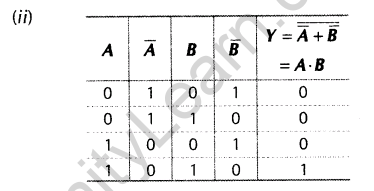
41.The two circuits shown here are a combination
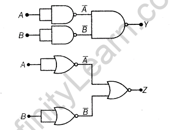
(i)Three NAND gates.
(ii)Three NOR gates.
Write truth tables for each of these combinations. [Delhi 2009 c]
Ans.
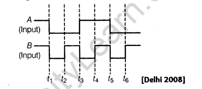
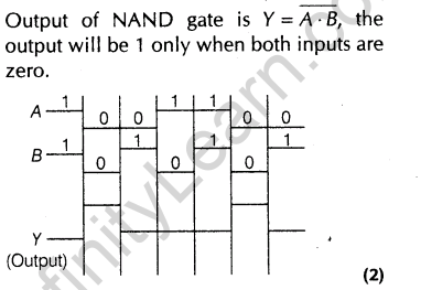
42.The given inputs A, B are fed to a 2-input NAND gate. Draw the output waveform of the gate.
Ans.
43.In the output of a 2-input NOR gate is fed as both inputs, A and B to another NOR gate, write down a truth table to find the final output, for all combinations of A, B.[Delhi 2008]
Ans.
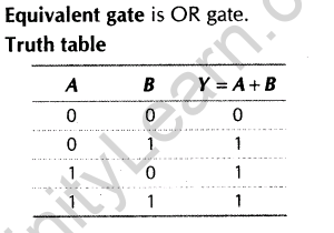
44.Write the truth table and draw the logic symbol of the gate for the circuit given as below:[Foreign 2008]

Ans.
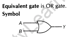
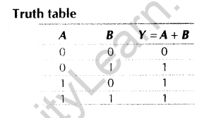
45. Write the truth table and draw the logic symbol of the gate for the circuit given as below: [Foreign 2008]

Ans.
3 Marks Questions
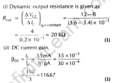
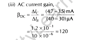
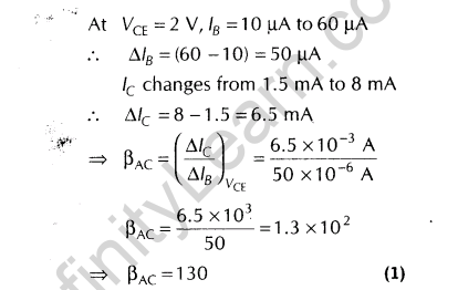
46.Output characteristics of an n-p-n transistor in CE configuration is -shown in the figure. Determine
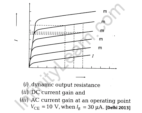
Ans.
47.You are given a circuit below. Write its truth table. Hence, identify the logic operation carried out by this circuit. Draw the logic symbol of the gate which Corresponds to [All India 2011]
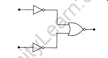
Ans.
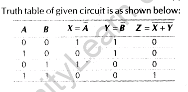
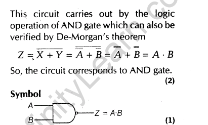
48.You are given a circuit below. Write its truth table. Hence, identify the logic operation carried out by this circuit. Draw the logic symbol of the gate which corresponds to[All India 2011]
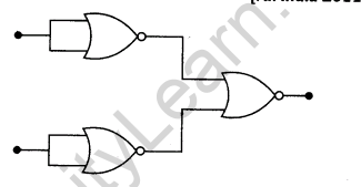
Ans.
![]()


49.Draw transfer characteristics of a common-emitter n-p-n Point out the region in which the transistor operates as an amplifier.
Define the following terms used in transistor amplifiers:
(i)Input resistance
(ii)Output resistance
(iii)Current amplification factor.[Foreign 2011]
Ans.


50.Draw the general shape of the transfer characteristics of a transistor in its CE Which regions of this characteristic of a transistor are used when it works as an amplifier?[All India 2010 C]
Ans.


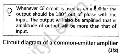
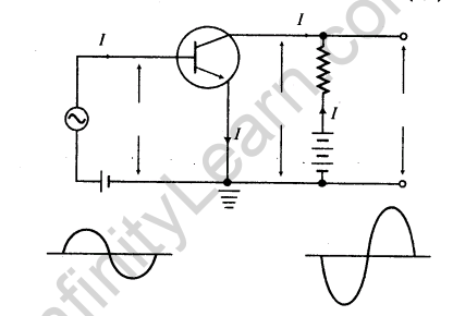
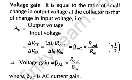
51.Give the circuit diagram of a common-emitter amplifier using an n-p-n transistor. Draw the input and output wave forms of the signal. Write the expression for its voltage gain. [HOTS, All India 2010]
Ans.
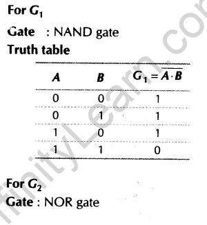
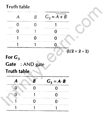
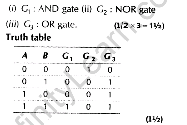
52.The inputs A and B shown here are used as the inputs for three different gates G1, G2 and G3. The outputs obtained in the three cases have the forms shown. Identify the three gates and write their truth tables. [All India 2009 c]
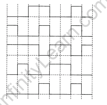
Ans.
53.The inputs A and B shown here are used as the inputs for’ three different gates G1, G2 and G3 one by one. The outputs obtained in the three cases have the forms shown. Identify the three gates and write their symbols. [All India 2009 C]
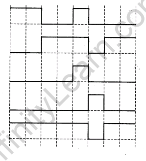
Ans.
54.Draw the labelled circuit diagram of a common-emitter transistor amplifier. Explain clearly, how the input and output signals are in opposite phase?[All India 2009]
Ans.


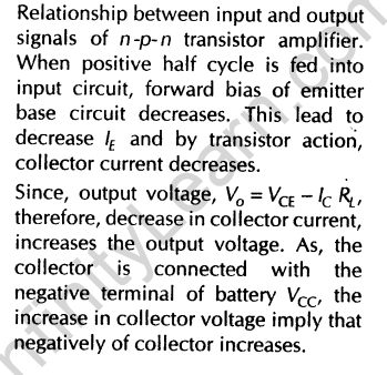
Thus, corresponding to positive half cycle of input AC, a negative amplified cycle is obtained at collector and vice-versa. This shows that output and input signals are in opposite phase
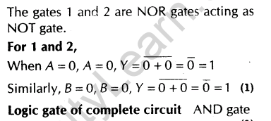
55.The inputs A and B are inverted by using two NOT gates and their outputs are fed to the NOR gate as shown below:
Analyse the action of the gates (1) and (2) and identify the logic gate of the complete circuit so obtained. Give its symbol and the truth table.[All India 2009]
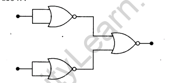
Ans.

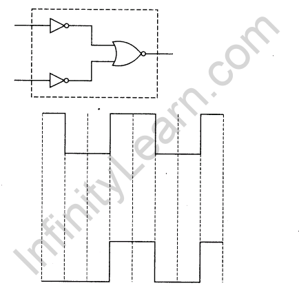
56.Identify the gate equivalent to the dotted box shown here and give its symbol and truth table The input A shown here is used with another unknown input B in this set up. If the output Y has the form shown, give the intervals over which the input B is in its high state. [Delhi 2008 C]
Ans.


B is in high state in the interval 3 to 4, 4 to 5 and 7 to 8.
5 Marks Questions
57.(i) Differentiate between three segments of a transistor on the basis of their size and level of doping.
(ii)How is a transistor biased to be in active state?
(iii)With the help of necessary circuit diagram, describe briefly, how n-p-n transistor in CE configuration amplifies a small sinusoidal input voltage. Write the expression for the AC current gain. [Delhi 2014]
Ans.(i) The base region of the transistor is physically located between the emitter and the collector region and is made from lightly doped high resistivity material. The emitter and collector regions are heavily doped. But the doping level in emitter is slightly greater than that of collector and the area of collector region is slightly more than that of emitter.
In term of doping level,
Emitter region > collector region > base region
In term of area of the region,
Collector region > emitter region > base region.The area of the collector region is greater than that of emitter. This is because the collector region has to handle more power than the emitter and also it has to collect more number of charge carriers to constituent the current. Emitter is heavily doped to provide large member of majority charge carriers, while base and collector are lightly doped to accept these charge carriers from emitter.
(ii) The conditions of a transistor for to be in active state are below:
(a)The input circuit should be forward biased by using a low voltage battery.
(b)The output circuit should be reverse biased by using a high voltage battery.
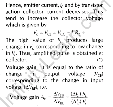
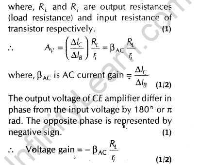
(iii) CE configuration While finding gain for CE configuration we should mind that it will depend upon the load resistance, input resistance as well as output will be inverted.


Working In the circuit, emitter is forward biased and collector is reversed biased. This makes input resistance (Rin) very low and output resistance (Rout) high. During the positive half cycle of input AC decrease the forward bias.
58.(i)Explain briefly with the help of a circuit diagram, how an n-p-n transistor in CE configuration is used to study input and output characteristics.
(ii) Describe briefly the underlying principle of a transistor amplifier working as an oscillator. Hence, use the necessary circuit diagram to explain how self sustained oscillations are achieved in the oscillator. [Delhi 2014 C]
Ans.(i) Common-emitter Transistor Characteristics
To study the characteristics of an n-p-n transistor in common-emitter mode, required circuit is shown in the figure. Here, base-emitter circuit is forward biased with battery VBE and emitter- collector circuit is reverse biased with battery Vcc.
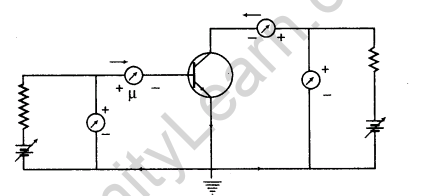
From circuit diagram, we come across to know that it is made up of two sections, i.e. input and output.
These two characteristics can be studied as shown below:
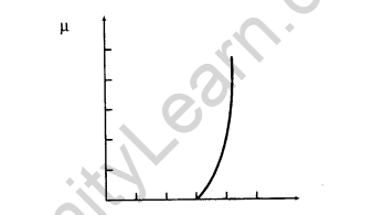
(a) Emitter or Input Characteristics
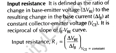
A graphical relation between the emitter voltage and the emitter current by keeping collector voltage constant is called input characteristics of the transistor.
Adjust collector-emitter voltage at a suitable high value VCE (say = + 10 V). It is necessary so as to make the base-collector junction reverse biased.
Now, with the help of rheostat gradually increases, the value of base-emitter voltage VBE in small steps and note the corresponding values of base current lB.
(ii) Feedback When a portion of the output power is returned back to the input in phase this is termed as positive feedback.
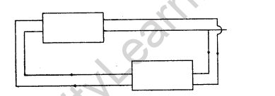
Feedback network The phenomenon of mutual inductance is used to take a part of output in coil L’ back into input coil L. When the switch K is closed, collector current begin to flow through L’, which in turn increases the magnetic flux linked with L’ and hence with L This leads to produce an induce emf in L, which increases the forward bias. This also increases the base current and hence collector current along with the charging of capacitor takes place with upper plate as positive. This phenomenon is repeated again and again till the collector current reaches to its maximum value.
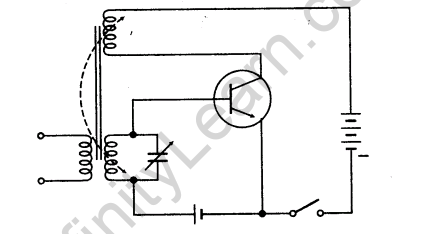
At maximum value of lc, current through L’ does not change and therefore flux remains unchanged and emf in L’ and L reduces to zero. Now, the discharging of capacitor begins through L. The positivity of upper plate decreases and forward bias decrease, which results in the form of decrease in base current and hence, decrease in collector current. This phenomenon repeats till collector current reduces to zero and emf in the coil L also reduces to zero.
Thus, the time duration in which collector current grows from zero to maximum, the current in coil L of tank circuit complete its half cycle. The duration in which collector current reduces from maximum to zero, the current in L’ completes its next half cycle
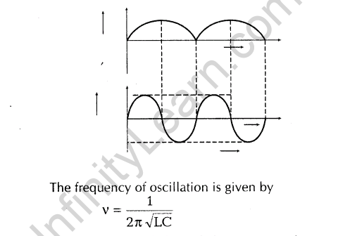
Thus, the AC of desired frequency and amplitude can be obtained by taking appropriate value of inductance,capacitance and strength of battery B
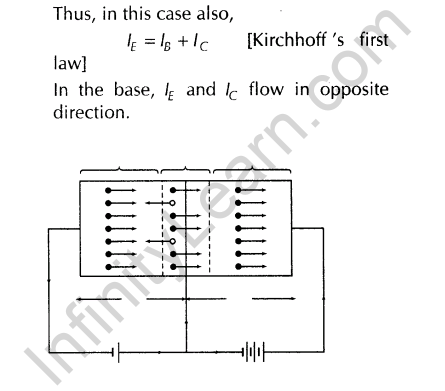
Ans.(i) In this transistor, the emitter-base junction is forward biased and its resistance is very low. So, the voltage of VEE is quite small.
The collector-base junction is reverse biased. The resistance of this junction is very high. So, the voltage of Vcc (VCB) is quite large (= 45 V). Electrons in emitter are repelled towards base by negative potential of VEE on emitter, resulting emitter current lE. The base being thin and lightly doped has low density of holes, thus when electrons enter the base region, then only a few holes get neutralised by electron hole combination, resulting in base current (IB). The remaining electrons pass over to the collector, due to high positive potential of collector, resulting in collector current (Ic) . As,’ e electron reaches to collector, it gets neutialised by the flow of one electron from the negative terminal of the battery Vcc to collector through connecting wire. Then, one electron flow from negative terminal of battery Vcc to positive terminal of battery VEE and one electron flow from negative terminal of VEE to emitter.
When the electron coming from emitter combines with the holes in base, then deficiency of hole in the base is compensated by the breaking of covalent bond there. The electron, so released flows to the positive terminal of battery VEE, through connecting wire.
Thus, in n-p-n transistor, the current is carried inside as well as in external circuit by the electrons
(ii) Common-emitter Transistor Characteristics
To study the characteristics of an n-p-n transistor in common-emitter mode, required circuit is shown in the figure. Here, base-emitter circuit is forward biased with battery VBE and emitter- collector circuit is reverse biased with battery Vcc.

From circuit diagram, we come across to know that it is made up of two sections, i.e. input and output.
These two characteristics can be studied as shown below:
(a) Emitter or Input Characteristics
A graphical relation between the emitter voltage and the emitter current by keeping collector voltage constant is called input characteristics of the transistor.
Adjust collector-emitter voltage at a suitable high value VCE (say = + 10 V). It is necessary so as to make the base-collector junction reverse biased.
Now, with the help of rheostat gradually increases, the value of base-emitter voltage VBE in small steps and note the corresponding values of base current lB.


(c) Feedback When a portion of the output power is returned back to the input in phase this is termed as positive feedback.

Feedback network The phenomenon of mutual inductance is used to take a part of output in coil L’ back into input coil L. When the switch K is closed, collector current begin to flow throughL’, which in turn increases the magnetic flux linked with L’ and hence with L This leads to produce an induce emf in L, which increases the forward bias. This also increases the base current and hence collector current along with the charging of capacitor takes place with upper plate as positive. This phenomenon is repeated again and again till the collector current reaches to its maximum value.

At maximum value of lc, current through L’ does not change and therefore flux remains unchanged and emf in L’ and L reduces to zero. Now, the discharging of capacitor begins through L. The positivity of upper plate decreases and forward bias decrease, which results in the form of decrease in base current and hence, decrease in collector current. This phenomenon repeats till collector current reduces to zero and emf in the coil L also reduces to zero.
Thus, the time duration in which collector current grows from zero to maximum, the current in coil L of tank circuit complete its half cycle. The duration in which collector current reduces from maximum to zero, the current in L’ completes its next half cycle

Thus, the AC of desired frequency and amplitude can be obtained by taking appropriate value of inductance,capacitance and strength of battery B
60.(i) Why is the base region of a transistor thin and lightly doped?
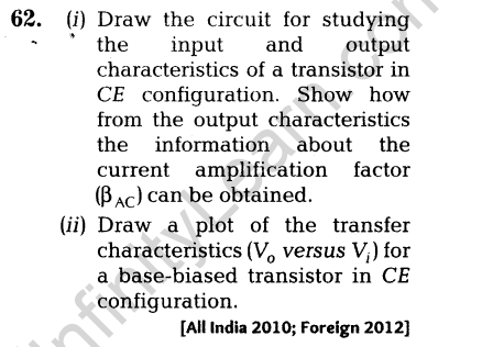
(ii) Draw the circuit diagram for studying the characteristics of an n-p-n transistor in common-emitter
configuration.Sketch the typical (a) input and (b) output characteristics in this configuration.
(iii)Describe briefly, how the output characteristics can be used to obtain the current gain in the transistor? [Delhi 2013 C]
Ans.(i) In this transistor, the emitter-base junction is forward biased and its resistance is very low. So, the voltage of VEE is quite small.
The collector-base junction is reverse biased. The resistance of this junction is very high. So, the voltage of Vcc (VCB) is quite large (= 45 V). Electrons in emitter are repelled towards base by negative potential of VEE on emitter, resulting emitter current lE. The base being thin and lightly doped has low density of holes, thus when electrons enter the base region, then only a few holes get neutralised by electron hole combination, resulting in base current (IB). The remaining electrons pass over to the collector, due to high positive potential of collector, resulting in collector current (Ic) . As,’ e electron reaches to collector, it gets neutialised by the flow of one electron from the negative terminal of the battery Vcc to collector through connecting wire. Then, one electron flow from negative terminal of battery Vcc to positive terminal of battery VEE and one electron flow from negative terminal of VEE to emitter.
When the electron coming from emitter combines with the holes in base, then deficiency of hole in the base is compensated by the breaking of covalent bond there. The electron, so released flows to the positive terminal of battery VEE, through connecting wire.
Thus, in n-p-n transistor, the current is carried inside as well as in external circuit by the electrons

(ii) Common-emitter Transistor Characteristics
To study the characteristics of an n-p-n transistor in common-emitter mode, required circuit is shown in the figure. Here, base-emitter circuit is forward biased with battery VBE and emitter- collector circuit is reverse biased with battery Vcc.

From circuit diagram, we come across to know that it is made up of two sections, i.e. input and output.
These two characteristics can be studied as shown below:
(a) Emitter or Input Characteristics
A graphical relation between the emitter voltage and the emitter current by keeping collector voltage constant is called input characteristics of the transistor.
Adjust collector-emitter voltage at a suitable high value VCE (say = + 10 V). It is necessary so as to make the base-collector junction reverse biased.
Now, with the help of rheostat gradually increases, the value of base-emitter voltage VBE in small steps and note the corresponding values of base current lB.


(c) Feedback When a portion of the output power is returned back to the input in phase this is termed as positive feedback.

Feedback network The phenomenon of mutual inductance is used to take a part of output in coil L’ back into input coil L. When the switch K is closed, collector current begin to flow through L’, which in turn increases the magnetic flux linked with L’ and hence with L This leads to produce an induce emf in L, which increases the forward bias. This also increases the base current and hence collector current along with the charging of capacitor takes place with upper plate as positive. This phenomenon is repeated again and again till the collector current reaches to its maximum value.

At maximum value of lc, current through L’ does not change and therefore flux remains unchanged and emf in L’ and L reduces to zero. Now, the discharging of capacitor begins through L. The positivity of upper plate decreases and forward bias decrease, which results in the form of decrease in base current and hence, decrease in collector current. This phenomenon repeats till collector current reduces to zero and emf in the coil L also reduces to zero.
Thus, the time duration in which collector current grows from zero to maximum, the current in coil L of tank circuit complete its half cycle. The duration in which collector current reduces from maximum to zero, the current in L’ completes its next half cycle

Thus, the AC of desired frequency and amplitude can be obtained by taking appropriate value of inductance,capacitance and strength of battery B
(iii)Circuit is as shown below:
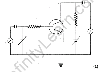
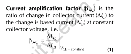
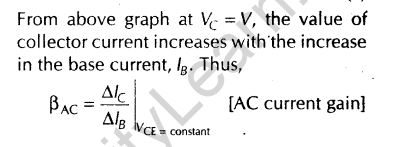
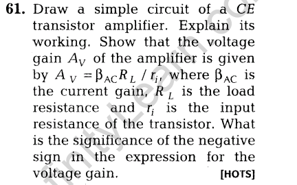
Ans.While finding gain for CE configuration we should mind that it will depend upon the load resistance, input resistance as well as output will be inverted.


Working In the circuit, emitter is forward biased and collector is reversed biased. This makes input resistance (Rin) very low and output resistance (Rout) high. During the positive half cycle of input AC decrease the forward bias.


Ans.Circuit is as shown below:


63.(i)Using the necessary circuit diagram, draw the transfer characteristics of a base-biased transistor in CE configuration. With the help of these characteristics, explain briefly how the transistor can be used as an amplifier?
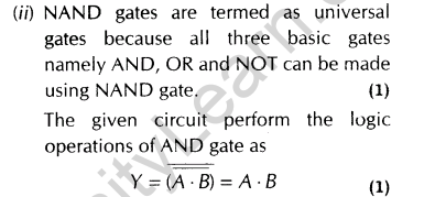
(ii) Why are NAND gate called universal gates? Identify the logical operations carried out by the circuit given as below:
Ans.(i)


Ans.(i) For n-p-n transistor in CE configuration circuit diagram

The transfer characteristic curve of base biased transistor in CE configuration as shown below:

65.(i)Draw the circuit diagram used for studying the input and output characteristics of an n-p-n transistor in the CE configuration. Show the typical shapes of these two characteristics.
(ii) How are the
(a)input resistance
(b)current amplification factor of the transistor determined from these characteristics?
[Delhi 2010 C]
Ans.(i) Common-emitter Transistor Characteristics
To study the characteristics of an n-p-n transistor in common-emitter mode, required circuit is shown in the figure. Here, base-emitter circuit is forward biased with battery VBE and emitter- collector circuit is reverse biased with battery Vcc.

From circuit diagram, we come across to know that it is made up of two sections, i.e. input and output.
These two characteristics can be studied as shown below:
(a) Emitter or Input Characteristics
A graphical relation between the emitter voltage and the emitter current by keeping collector voltage constant is called input characteristics of the transistor.
Adjust collector-emitter voltage at a suitable high value VCE (say = + 10 V). It is necessary so as to make the base-collector junction reverse biased.
Now, with the help of rheostat gradually increases, the value of base-emitter voltage VBE in small steps and note the corresponding values of base current lB.


(ii) Feedback When a portion of the output power is returned back to the input in phase this is termed as positive feedback.

Feedback network The phenomenon of mutual inductance is used to take a part of output in coil L’ back into input coil L. When the switch K is closed, collector current begin to flow through //, which in turn increases the magnetic flux linked with L’ and hence with L This leads to produce an induce emf in L, which increases the forward bias. This also increases the base current and hence collector current along with the charging of capacitor takes place with upper plate as positive. This phenomenon is repeated again and again till the collector current reaches to its maximum value.

At maximum value of lc, current through L’ does not change and therefore flux remains unchanged and emf in L’ and L reduces to zero. Now, the discharging of capacitor begins through L. The positivity of upper plate decreases and forward bias decrease, which results in the form of decrease in base current and hence, decrease in collector current. This phenomenon repeats till collector current reduces to zero and emf in the coil L also reduces to zero.
Thus, the time duration in which collector current grows from zero to maximum, the current in coil L of tank circuit complete its half cycle. The duration in which collector current reduces from maximum to zero, the current in L’ completes its next half cycle

Thus, the AC of desired frequency and amplitude can be obtained by taking appropriate value of inductance,capacitance and strength of battery B.
(ii)


66.(i)Draw a circuit diagram to study the input and output characteristics of an n -p- n transistor in its common- emitter configuration. Draw the typical input and output characteristics.
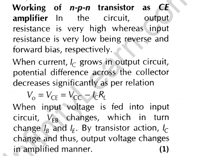
(ii) Explain with the help of a circuit diagram, the working of an n-p-n transistor as a common-emitter amplifier. [Delhi 2009 C]
Ans.(i) Common-emitter Transistor Characteristics
To study the characteristics of an n-p-n transistor in common-emitter mode, required circuit is shown in the figure. Here, base-emitter circuit is forward biased with battery VBE and emitter- collector circuit is reverse biased with battery Vcc.

From circuit diagram, we come across to know that it is made up of two sections, i.e. input and output.
These two characteristics can be studied as shown below:
(a) Emitter or Input Characteristics
A graphical relation between the emitter voltage and the emitter current by keeping collector voltage constant is called input characteristics of the transistor.
Adjust collector-emitter voltage at a suitable high value VCE (say = + 10 V). It is necessary so as to make the base-collector junction reverse biased.
Now, with the help of rheostat gradually increases, the value of base-emitter voltage VBE in small steps and note the corresponding values of base current lB.


(ii) Feedback When a portion of the output power is returned back to the input in phase this is termed as positive feedback.

Feedback network The phenomenon of mutual inductance is used to take a part of output in coil L’ back into input coil L. When the switch K is closed, collector current begin to flow through //, which in turn increases the magnetic flux linked with L’ and hence with L This leads to produce an induce emf in L, which increases the forward bias. This also increases the base current and hence collector current along with the charging of capacitor takes place with upper plate as positive. This phenomenon is repeated again and again till the collector current reaches to its maximum value.

At maximum value of lc, current through L’ does not change and therefore flux remains unchanged and emf in L’ and L reduces to zero. Now, the discharging of capacitor begins through L. The positivity of upper plate decreases and forward bias decrease, which results in the form of decrease in base current and hence, decrease in collector current. This phenomenon repeats till collector current reduces to zero and emf in the coil L also reduces to zero.
Thus, the time duration in which collector current grows from zero to maximum, the current in coil L of tank circuit complete its half cycle. The duration in which collector current reduces from maximum to zero, the current in L’ completes its next half cycle

Thus, the AC of desired frequency and amplitude can be obtained by taking appropriate value of inductance,capacitance and strength of battery B.
(ii)


67.Draw a circuit diagram of an n-p-n transistor with its emitter base junction forward biased and base- collector junction reverse biased. Describe briefly its working.
Explain, how a transistor in active state exhibits a low resistance at its emitter-base junction and high resistance at its base-collector junction? [Foreign 2009]
Ans. n-p-n transistor in CB configuration
Since, the base is common in input and output circuits, therefore transistor is connected in CB configuration.
Working When input voltage, VBE is sufficient to make flow of emitter current, collector current flows in output circuit. In this condition, the circuit is said to be in active state.
The small change in VEB, produces sufficient change in emitter current and hence, in collector current. The input circuit offers very small resistance as ample change in emitter current occurs corresponding to small change in input voltage.
This lead to produce large change in output voltage inspite of smaller change in collector current (lE < lc). This shows that output circuit offer high resistance
68.Draw a labelled circuit diagram of a base-biased transistor in common-emitter configuration. Plot the transfer characteristics of this base biased transistor indicating the different regions of its operation.[Delhi 2009 c]
Ans.


Ans.(i)


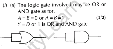
70.(i) The same input -a! is applied to both the (input) terminals of a given logic gate. If the output is(a)same as the (common) input signal.
(b)inverted with respect to the (common) input signal.
Identify the logic gates involved in each case.
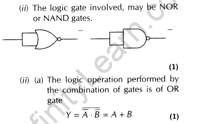
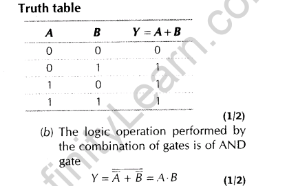
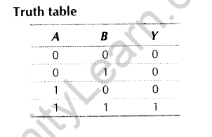
(ii) Write the truth tables for each of the combinations shown below. Also identify the logic operations performed by them. [All India 2008 C]

Ans.
